Textile holding frame

Inactive Publication Date: 2001-04-03
ENGLE ROSEMARY E
View PDF10 Cites 23 Cited by
  • Summary
  • Abstract
  • Description
  • Claims
  • Application Information

AI Technical Summary

Problems solved by technology

These tensioned the quilt adequately, and were inexpensive, but were awkward, essentially immobile, required basting of the quilt "sandwich" before actual quilting, and took up a large amount of space.
Although generally satisfactory, the most sophisticated wooden frames using the two, three or four rotating pole design are often expensive to produce, large, immobile, heavy, and difficult to assemble for use and to disassemble for storage.
However, the crescent shaped clamp members disclosed in the '522 patent can be difficult to install, and because of the snap fit and lack of a place to grip the clamp can be quite diffi

Method used


Image

  • Textile holding frame
  • Textile holding frame
  • Textile holding frame

Examples


Embodiment Construction

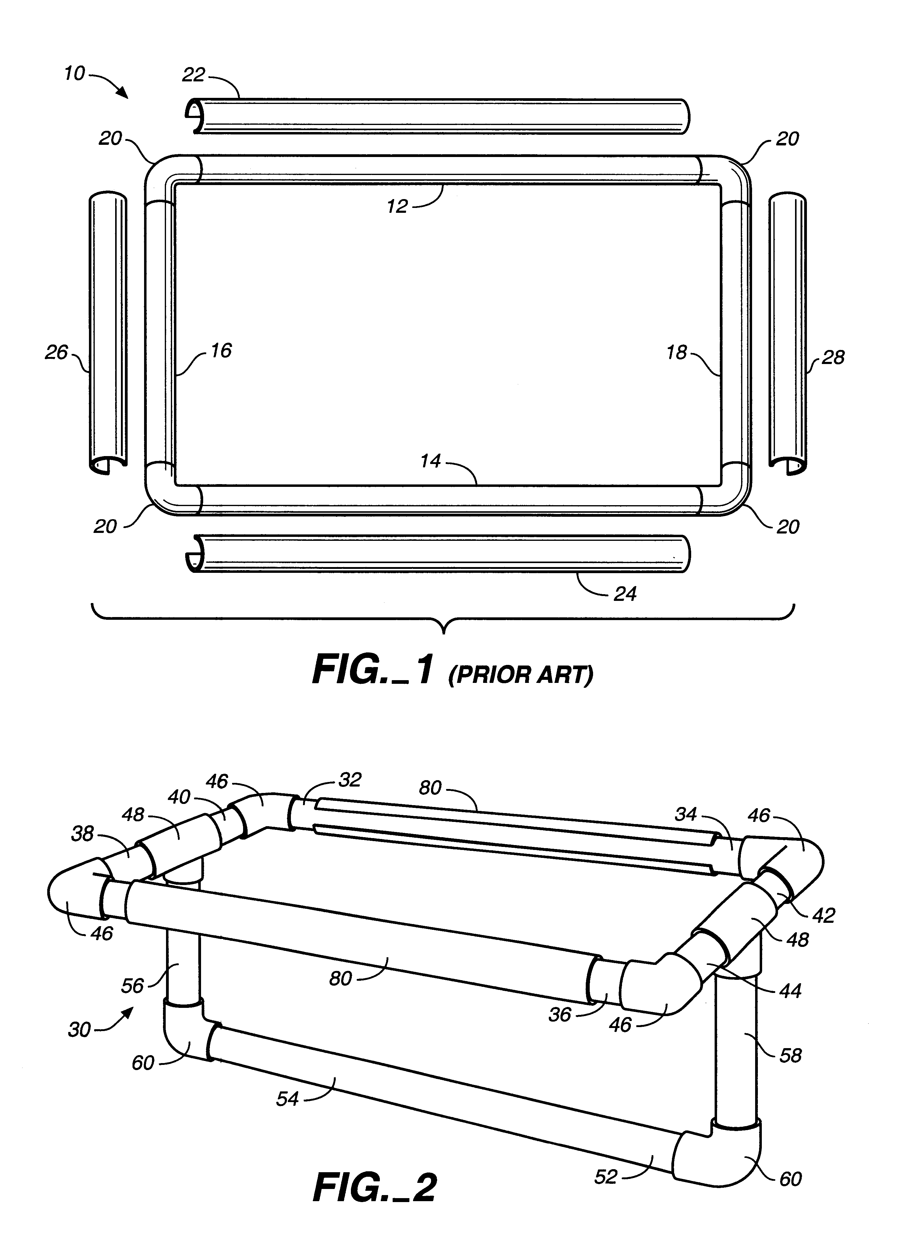
Referring now to the drawings, and particularly to FIG. 1 thereof, there is shown a quilting / textile frame of the type disclosed in Kramer U.S. Pat. No. 4,658,522. The quilting frame 10 comprises lateral members 12 and 14 and side members 16 and 18 all formed from PVC tubing. Four elbows 20 also formed from PVC tubing interconnect the lateral members 12 and 14 and permanently connect the side members 16 and 18 to define a rectangular configuration. Clamping members 22, 24, 26 and 28 function to secure material to be quilted in engagement with the lateral members 12 and 14 and the side members 16 and 18, respectively. The clamping members 22, 24, 26 and 28 comprise lengths of PVC tubing which are slit lengthwise to define a C-shaped cross-sectional configuration. A further understanding of the construction and operation of that quilting frame may be had by reference to U.S. Pat. No. 4,658,522, the disclosure of which is incorporated herein by reference.

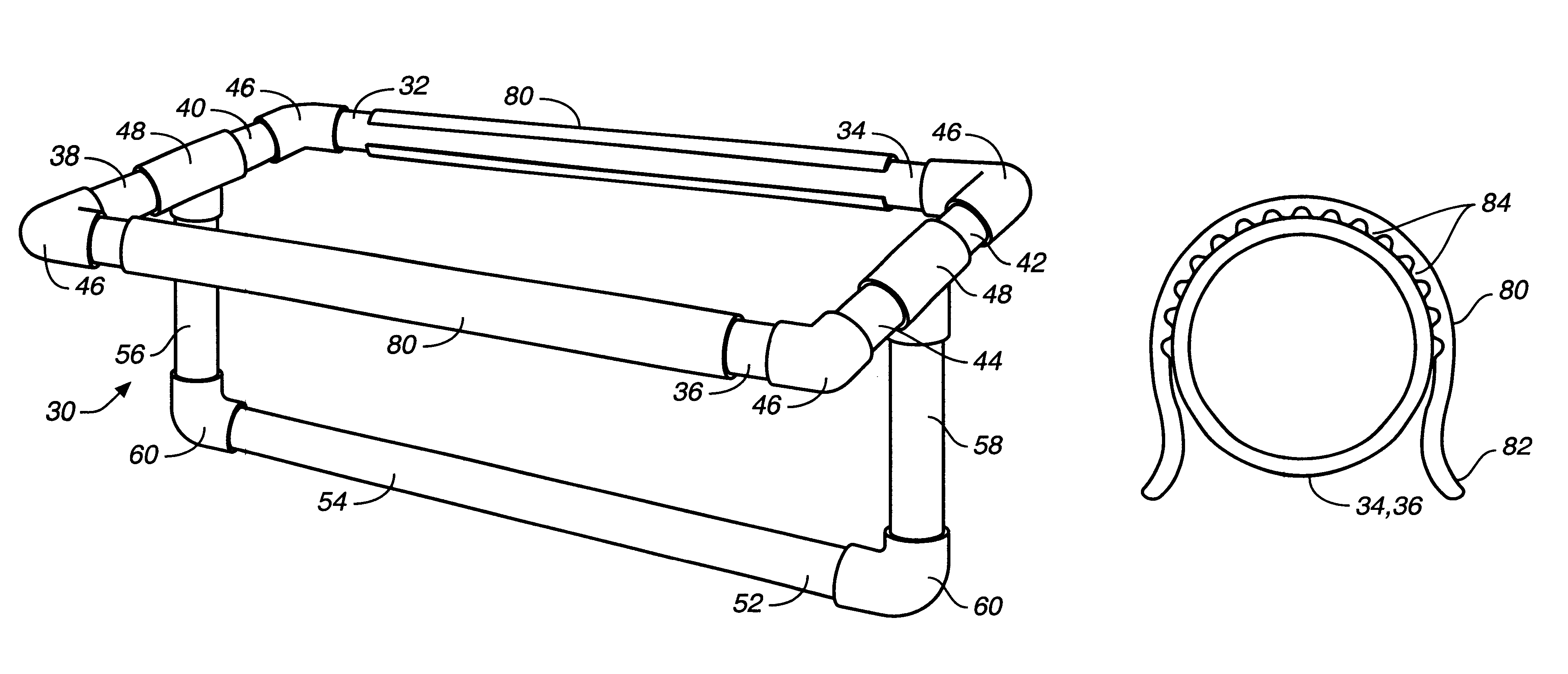
Referring now to FIG. 2, there ...


PUM

PropertyMeasurementUnit
Tensionaaaaaaaaaa

Abstract

A textile or other material holding frame portion having a pair of side members and two or more lateral members extending between the sides to define a generally rectangular configuration. One embodiment uses stationary frame members with retainers for material retention and/or tensioning, and another embodiment uses rotating frame members to provide the desired tensioning. Both embodiments may include pressure joints and/or slip joints, be self-supporting, table supported or utilize a base support.

Description

1. Field of the InventionThis invention relates generally to quilting, needlework and other textile holding frames, and more particularly to improvements in the art of textile holding frames to facilitate the support, retention, and / or tensioning of the textile or other materials for comfortable and efficient use, and the maintenance of proper tension on the textile or other materials to be worked.2. Description of the Prior ArtQuilting frames and other textile supporting frames have traditionally been constructed from various types of wood, and have frequently included some form of structure for orienting the materials to be worked into a comfortable position for the user. The simplest wooden frames were four lengths of wood arranged in a rectangle, temporarily attached at the corners with metal clamps usually supported on chairs over which was stretched the basted quilt to be worked. These tensioned the quilt adequately, and were inexpensive, but were awkward, essentially immobile...

Claims


Application Information

Patent Timeline
IPC IPC(8): D05C1/00D05C1/02
CPCD05C1/02
Inventor ENGLE, ROSEMARY E.
Owner ENGLE ROSEMARY E
Why Eureka
Try Eureka