Lip seal for sealing cylindrical surfaces

a technology for cylindrical surfaces and seals, applied in the direction of engine seals, fluid actuated clutches, non-mechanical actuated clutches, etc., can solve the problems of unable to fix the lip seal in its position by a ring groove or rule ou

Inactive Publication Date: 2001-04-03
MANNESMANN SACHS AG
View PDF13 Cites 39 Cited by
  • Summary
  • Abstract
  • Description
  • Claims
  • Application Information

AI Technical Summary

Problems solved by technology

The thin dimensions make it impossible to fix the lip seal in its position by a ring groove or to rule out tilting movements of the lip seal which occur due to the movement of an inner piston relative to the housing, in which the lip seal is arranged.

Method used


Image

  • Lip seal for sealing cylindrical surfaces
  • Lip seal for sealing cylindrical surfaces

Examples


Embodiment Construction

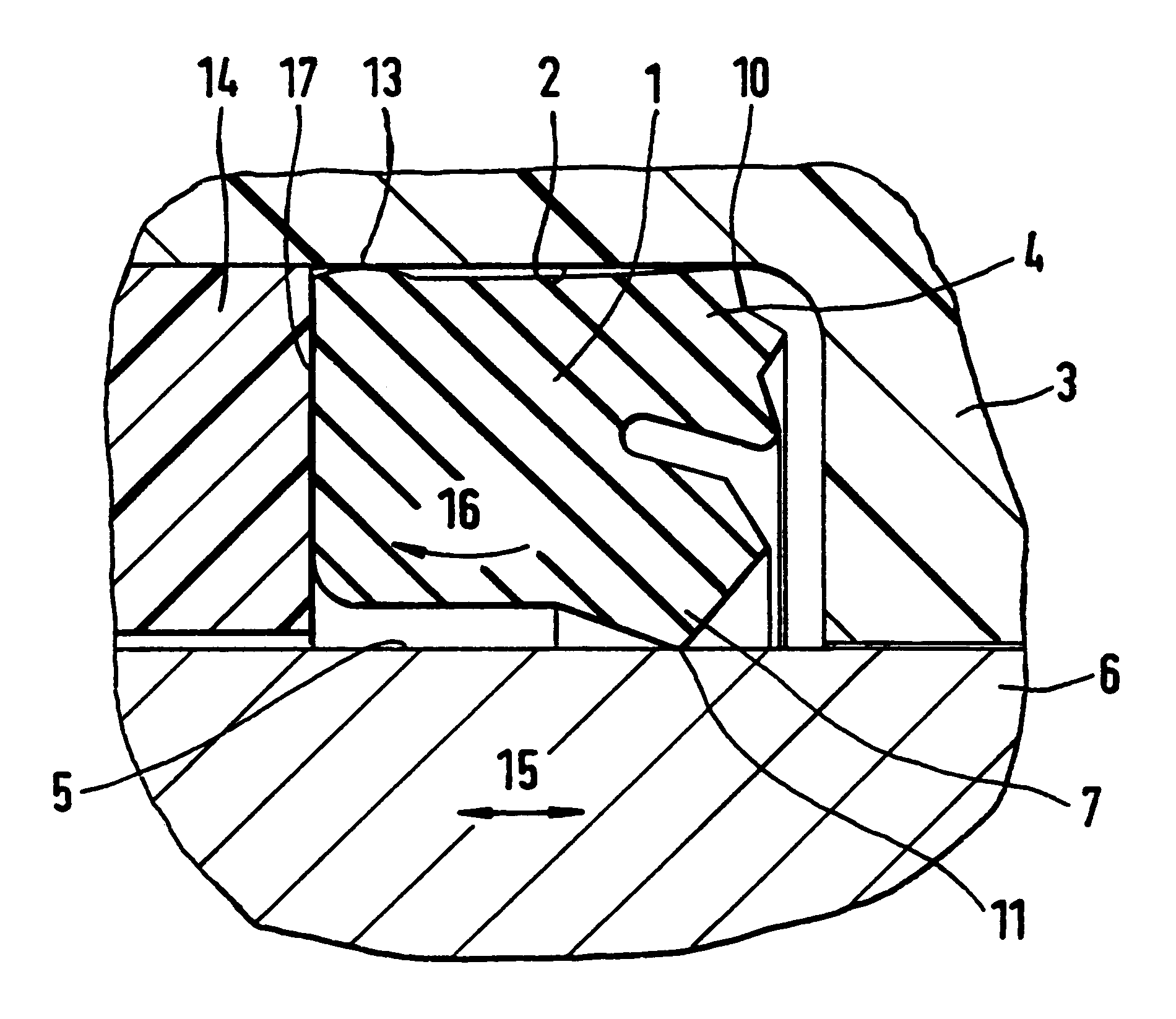
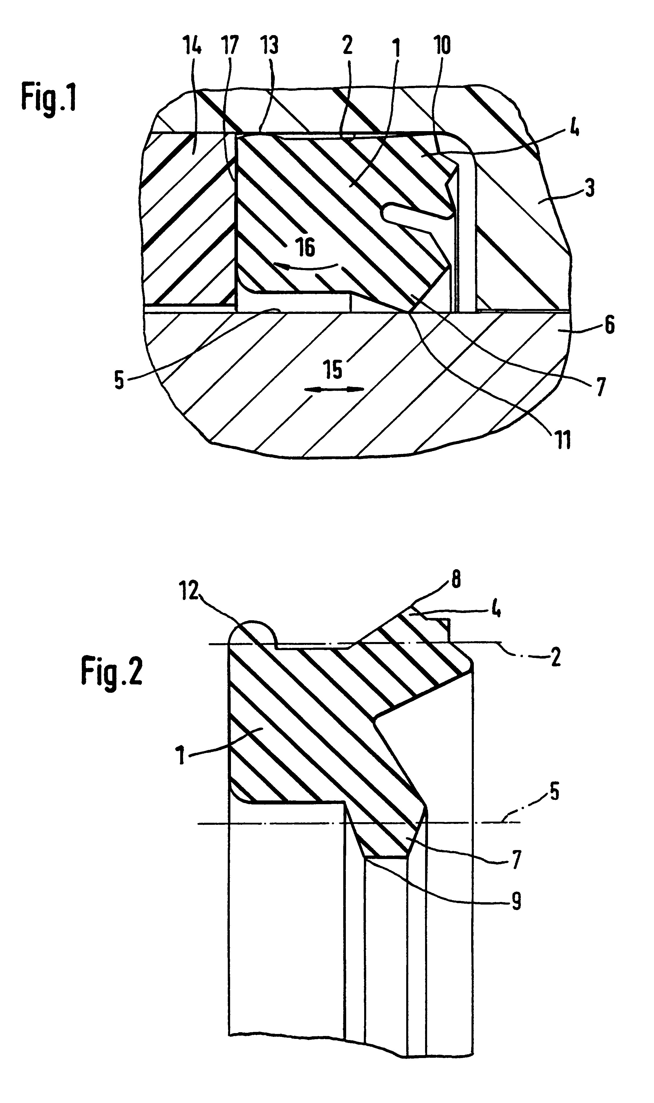
Referring to FIGS. 1 and 2, a lip seal 1 for sealing cylindrical surfaces, is intended for installation in a cylindrical part 2 of a housing 3. This embodiment of the lip seal 1 carries a first, outwardly directed sealing lip 4 and a second, inwardly directed sealing lip 7. The first sealing lip 4 has an outer sealing edge 8, and the second sealing lip 7 has an inner sealing edge 9. In FIG. 1, the lip seal 1 is secured in the housing 3 with a stop ring 14, which has a ring-shaped stop surface 17 that is in contact with a plane-parallel front face of the lip seal 1. A piston 6 is axially movably arranged in a boring of the housing 3 for moving in a movement direction 15.

In FIG. 2, sealing lip 1 is in a relaxed state in which the diameter of the first sealing lip 4 extends farther out past the position normally occupied by the cylindrical part 2 of the housing. Similarly, the second sealing lip 7 extends radially far inward past the position normally occupied by the cylindrical surfac...


PUM


Abstract

A lip seal for sealing cylindrical surfaces of a cylindrical housing and a axially movable piston within the housing includes an annularly arranged supporting bead on its outer diameter to improve its tilting behavior around a central axis running annularly through the center of the lip seal. A first sealing lip of the lip seal forms a seal on the cylindrical surface of the housing and a second sealing lip forms a seal on the cylindrical surface of the piston. The supporting bead, in the installed state, forms a contact seal in the cylindrical part of the housing. Together with the contact seals of the first sealing lip and the second sealing lip, the supporting bead lends stability against tilting to the lip seal. Advantageously, a good sealing quality of the lip seal is maintained during an increased number of load changes.

Description

1. Field of the InventionThe invention relates to a lip seal for sealing cylindrical surfaces, especially those of input and output hydraulic cylinders in motor vehicles, axially fixed in a cylindrical part of a cylinder housing with a first sealing lip directed against the cylinder housing and a second sealing lip directed against a cylindrical surface of a piston which is axially movably within the cylinder housing.2. Description of the Related ArtGerman reference DE 195 23 011 A1 discloses a hydraulic clutch release device for a friction clutch having a housing. A telescopic piston including a primary piston and a secondary piston is arranged in a central recess, of the housing for the purpose of attaining reduced structural length. The primary piston has a lip seal with an inwardly directed sealing lip and an outwardly directed sealing lip on its ring-shaped front face. The lip seal is mounted and held in its position with the primary piston in an annular groove in the front fac...

Claims


Application Information

Patent Timeline
Patent Type & Authority Patents(United States)
IPC IPC(8): F16D25/00F16D25/12F16J15/32F16J15/3236
CPCF16D25/12F16J15/3236
Inventor RIESS, THOMAS
Owner MANNESMANN SACHS AG
Why Eureka
Try Eureka