Lip seal for roller cone drill bit

a drill bit and roller cone technology, applied in drilling machines, cutting machines, construction, etc., can solve the problems of irregular application, large load carried by internal bearings, and significant drilling budget expens

Active Publication Date: 2005-03-17
GP USA HLDG LLC
View PDF85 Cites 25 Cited by
  • Summary
  • Abstract
  • Description
  • Claims
  • Application Information

AI Technical Summary

Problems solved by technology

One trip can require many man-hours and, thus, tripping is a significant expense of the drilling budget.
Thus, the loads carried by the internal bearings can be very large and irregularly applied.
One

Method used


Image

  • Lip seal for roller cone drill bit
  • Lip seal for roller cone drill bit
  • Lip seal for roller cone drill bit

Examples


Embodiment Construction

[0020] Illustrative embodiments of the invention are described below. In the interest of clarity, not all features of an actual implementation are described in this specification. It will, of course, be appreciated that in the development of any such actual embodiment, numerous implementation-specific decisions must be made to achieve the developers” specific goals, such as compliance with system-related and business-related constraints, which will vary from one implementation to another. Moreover, it will be appreciated that such a development effort might be complex and time-consuming, but would nevertheless be a routine undertaking for those of ordinary skill in the art having the benefit of this disclosure.

[0021] The present invention will now be described with reference to the attached drawings which are included to describe and explain illustrative examples of the present invention. The words and phrases used herein should be understood and interpreted to have a meaning consi...


PUM


Abstract

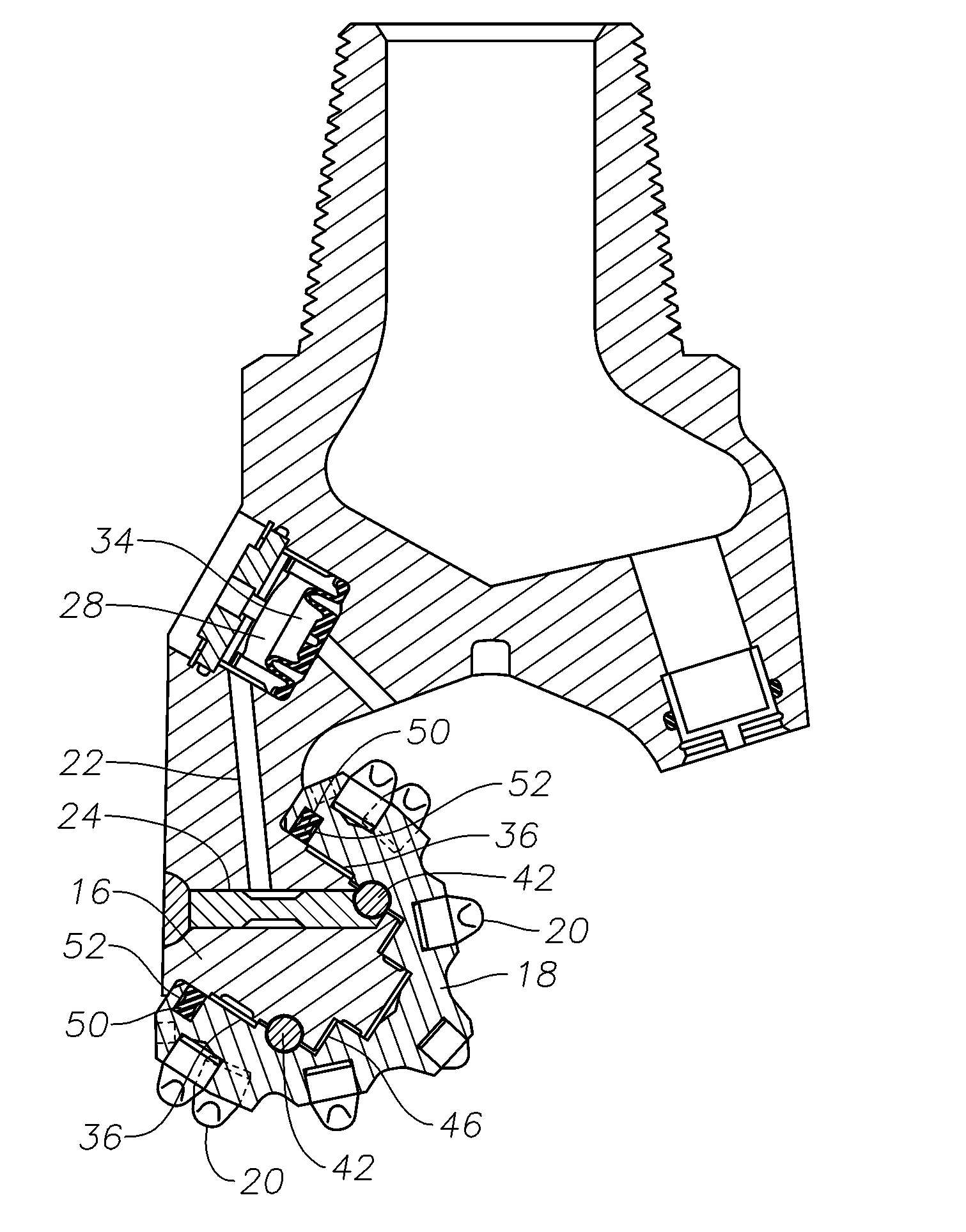
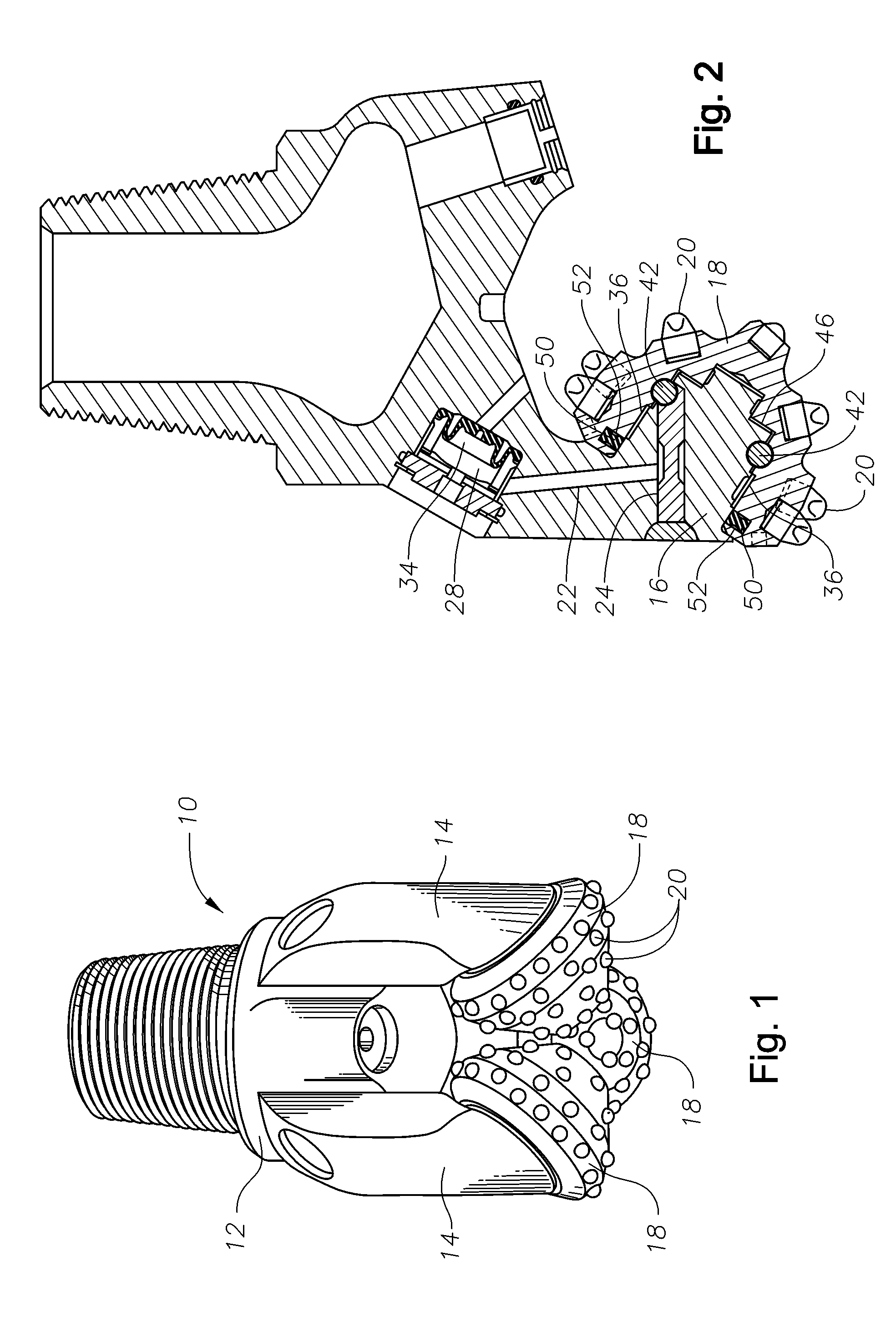
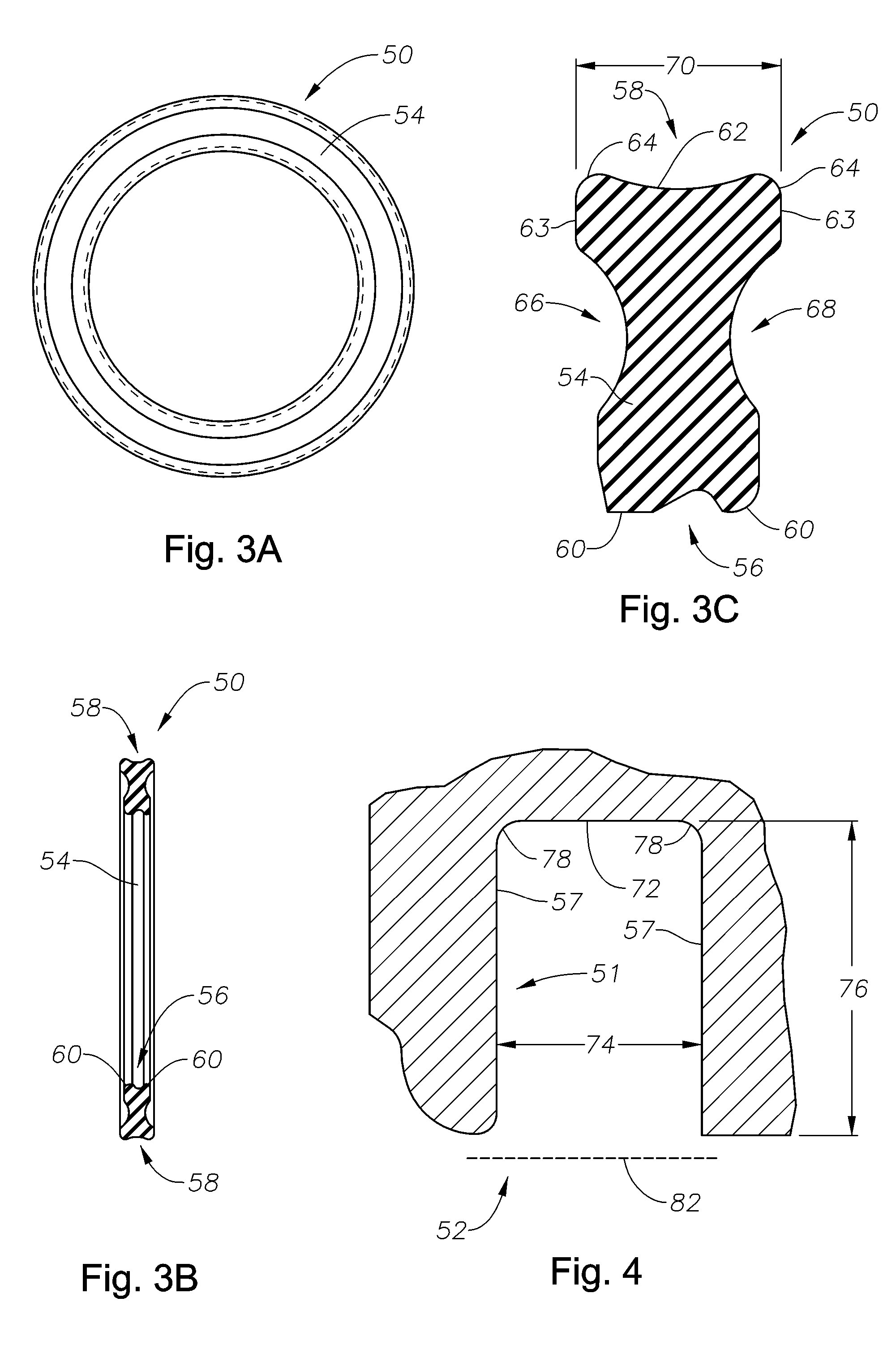
The present invention is generally directed to various embodiments of a radial lip seal for use with roller cone drill bits. In one illustrative embodiment, a drill bit is disclosed that is comprised of a spindle, a rolling cutter positioned around the spindle, the rolling cutter having a seal recess formed therein, the seal recess having an outer surface, and a lip seal positioned in the seal recess and around the spindle, wherein at least one void is intentionally established between the outer surface of the seal recess and the outer surface of the lip seal. In another illustrative embodiment, the method comprises providing a drill bit comprised of a spindle, a rolling cutter positioned around the spindle, the rolling cutter having a seal recess formed therein, the seal recess having an outer surface, and a lip seal positioned in the seal recess and around the spindle, wherein at least one void is intentionally created between the outer surface of the seal recess and the outer surface of the lip seal. The method further comprises positioning the drill bit in a well bore, wherein the at least one void is at least partially collapsed when the drill bit is subjected to hydrostatic pressure in the well bore, and performing drilling operations with the drill bit.

Description

BACKGROUND OF INVENTION [0001] 1. Field of the Invention [0002] The present invention is generally directed to the field of sealing technology for roller cone drill bits, and, more particularly, to a radial lip seal that may be used on a roller cone drill bit. [0003] 2. Description of the Related Art [0004] Oil and gas wells are formed by a rotary drilling process. To that end, a drill bit is mounted on the end of a drill string which may be very long, e.g., several thousand feet. At the surface, a rotary drive mechanism turns the drill string and the attached drill bit at the bottom of the hole. In some cases, a downhole motor may provide the desired rotation to the drill bit. During drilling operations, a drilling fluid (so-called drilling mud) is pumped through the drill string and back up-hole by pumps located on the surface. The purpose of the drilling fluid is to, among other things, remove the earthen cuttings resulting from the drilling process. [0005] When the drill bit wea...

Claims


Application Information

Patent Timeline
IPC IPC(8): E21B10/22E21B10/25
CPCE21B10/25
Inventor BURR, BRUCE H.
Owner GP USA HLDG LLC
Why Eureka
Try Eureka