Methods for increasing production from a wellbore

Inactive Publication Date: 2008-01-22
WEATHERFORD TECH HLDG LLC
View PDF23 Cites 61 Cited by
  • Summary
  • Abstract
  • Description
  • Claims
  • Application Information

AI Technical Summary

Benefits of technology

[0009]The present invention generally relates to a method for recovering productivity of an existing well. First, an assembly is inserted into a wellbore, the assembly includes a tubular member for transporting drilling fluid downhole and an under-reamer disposed at the end of the tubular member. The under reamer includes blades disposed on a front portion and a rear portion. Upon insertion of the assembly, an annulus is created between the assembly and the wellbore. Next, the assembly is positioned near a zone of interest. Drilling fluid is pumped down the tubular member and exits out ports in the under-reamer. The drilling fluid is used to create an under balanced condition where a hydrostatic pressure in the annulus is below the formation pressure at a zone of interest. The under-reamer is activated, thereby allowing the blades on the front portion to contact the wellbore diameter. The tubular member urges the activated under-reamer downhole to enlarge the wellbore diameter and remove a layer of skin for a predetermined length. During the under-reaming operation, its underbalance condition allows the wellbore fluid to migrate up the annulus and out of the wellbore. After the under-reamer has removed the skin and a portion of the formation, back-reaming may be performed to remove any excess wellbore material, drill cuttings and fines left over from the under-reaming operation. The under balanced back-reaming operation ensures no additional skin damage is formed in the wellbore. Upon completion, the under-reamer is deactivated and the assembly is removed from the wellbore.

Problems solved by technology

During the under-reaming operation, its underbalance condition allows the wellbore fluid to migrate up the annulus and out of the wellbore.

Method used


Image

  • Methods for increasing production from a wellbore
  • Methods for increasing production from a wellbore
  • Methods for increasing production from a wellbore

Examples


Embodiment Construction

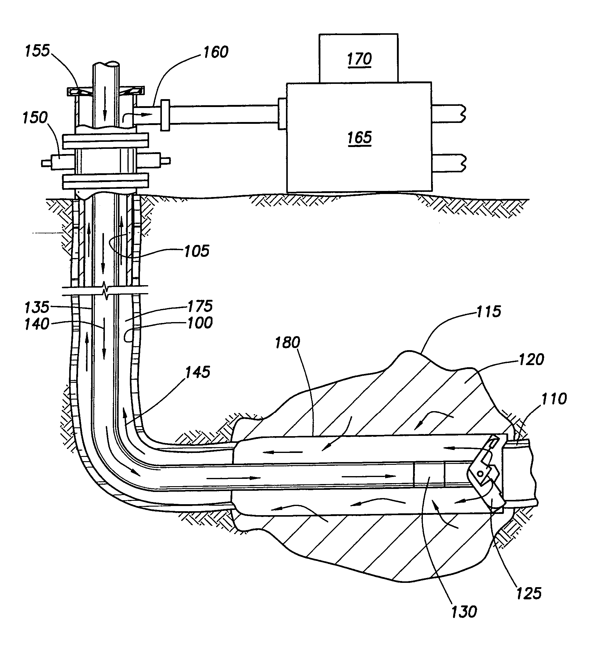
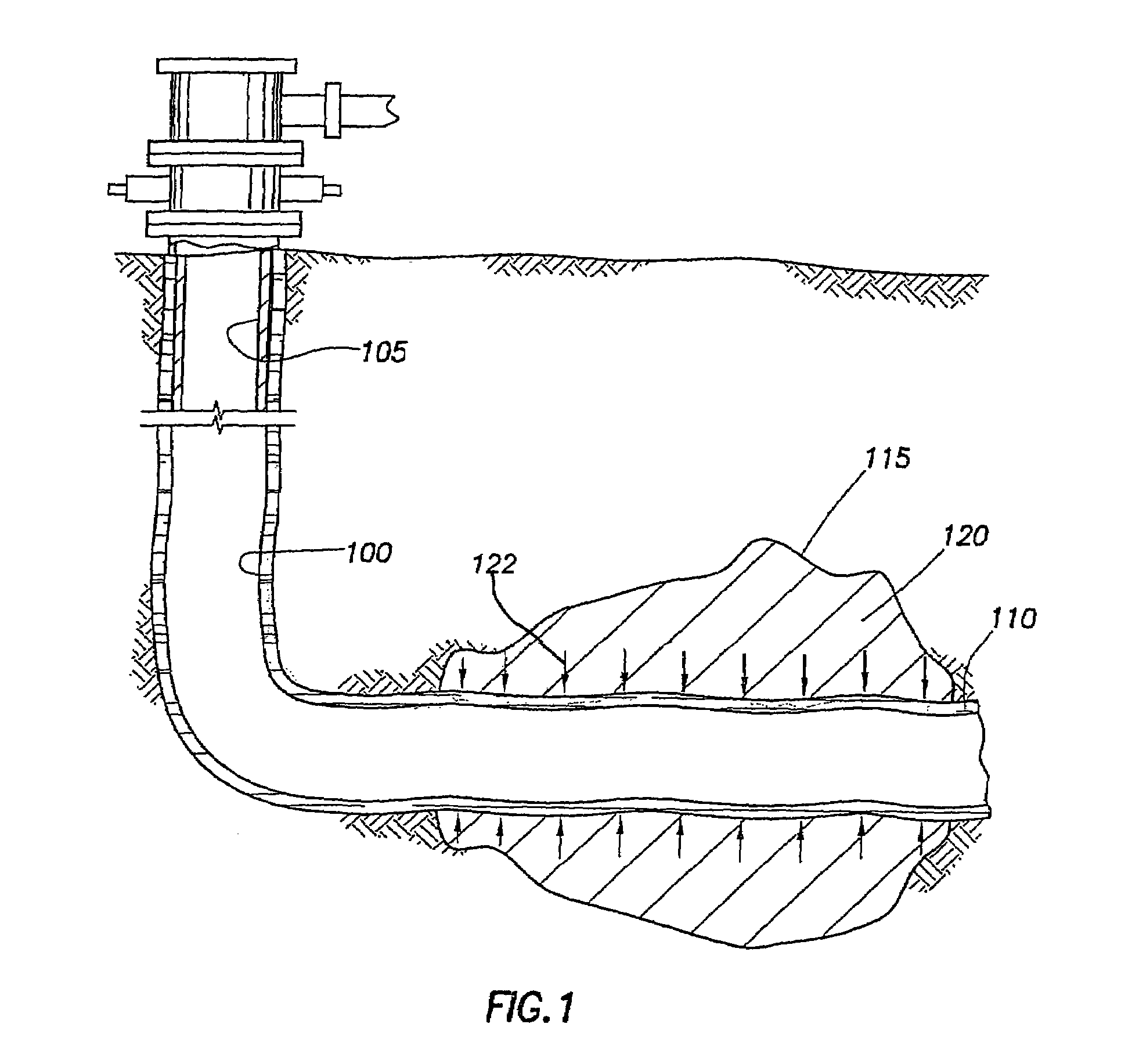
[0018]FIG. 1 is a cross-sectional view of a wellbore 100 having a layer of skin 110 on the surface thereof. As illustrated, a horizontal portion of wellbore 100 is uncased adjacent a formation 115 and is lined with casing 105 at the upper end. The uncased portion is commonly known in the industry as a “barefoot” well. It should be noted that this invention is not limited to use with uncased horizontal wells but can also be used with cased and vertical wellbores. The layer of skin 110 is created throughout the diameter of the wellbore 100 in the initial overbalanced drilling operation of the wellbore 100. The skin 110 clogs the wellbore 100, thereby restricting the flow into the wellbore 100 of formation fluid 120 as illustrated by arrow 122. Because the skin 110 restricts the flow of formation fluid 120, the skin 110 is said to have a positive skin factor.

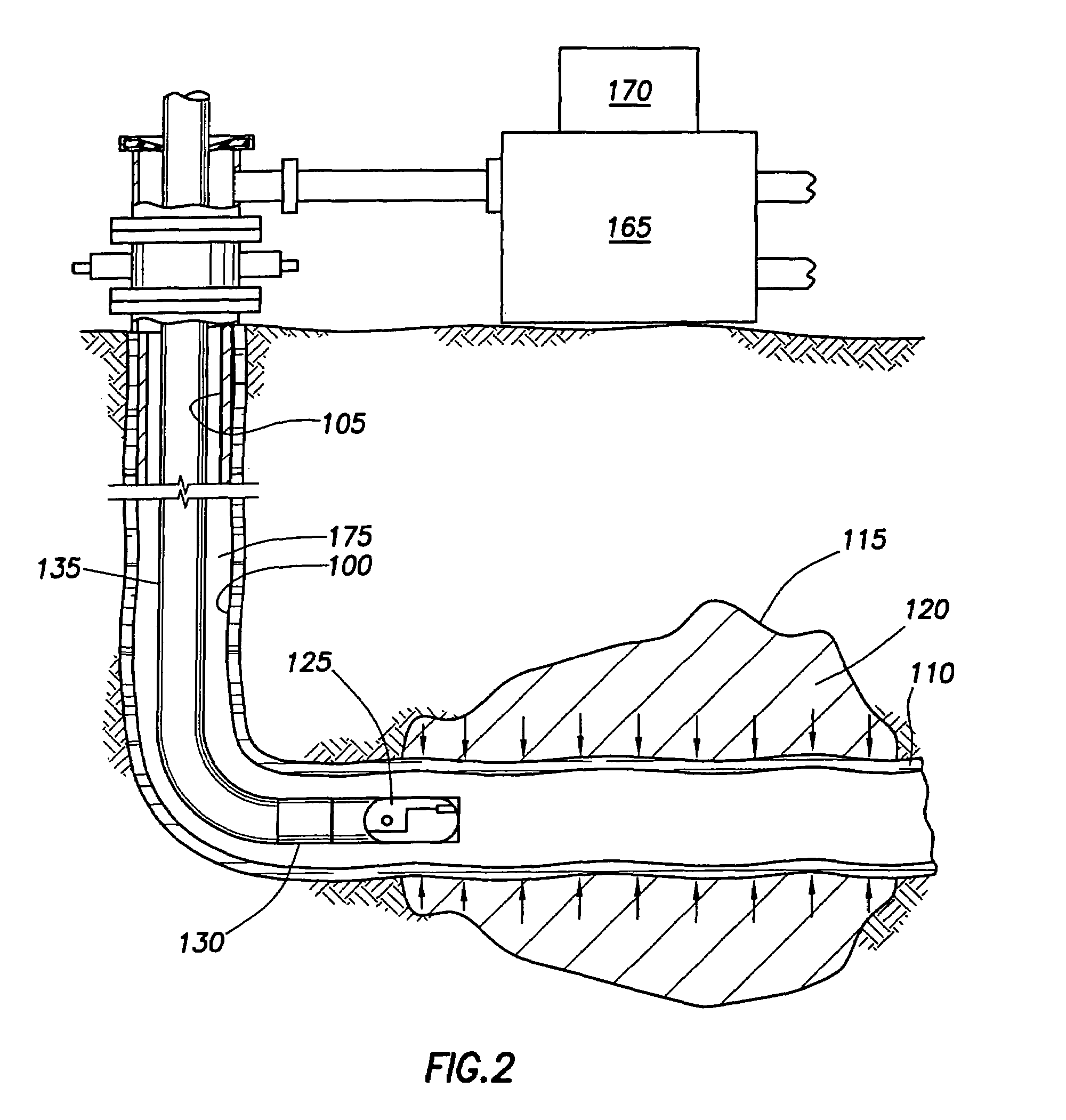
[0019]FIG. 2 is a cross-sectional view of the wellbore 100 illustrating an under-reamer 125 positioned at a predetermined locatio...


PUM


Abstract

The present invention generally relates to a method for recovering productivity of an existing well. First, an assembly is inserted into a wellbore, the assembly includes a tubular member for transporting drilling fluid downhole and an under-reamer disposed at the end of the tubular member. Upon insertion of the assembly, an annulus is created between the assembly and the wellbore. Next, the assembly is positioned near a zone of interest and drilling fluid is pumped down the tubular member. The drilling fluid is used to create an underbalanced condition where a hydrostatic pressure in the annulus is below a zone of interest pressure. The under-reamer is activated to enlarge the wellbore diameter and remove a layer of skin for a predetermined length. During the under-reaming operation, the hydrostatic pressure is maintained below the zone of interest pressure, thereby allowing wellbore fluid to migrate up the annulus and out of the wellbore. After the under-reaming operation, back-reaming may be performed to remove any excess wellbore material, drill cuttings and fines left over from the under-reaming operation and to ensure no additional skin damage is formed in wellbore. Upon completion, the under-reamer is deactivated and the assembly is removed from the wellbore.

Description

CROSS-REFERENCE TO RELATED APPLICATIONS[0001]This application is a continuation of U.S. patent application Ser. No. 10 / 127,325, filed Apr. 22, 2002, now Pat. No. 6,810,960. The aforementioned related patent application is herein incorporated by reference in its entirety.BACKGROUND OF THE INVENTION[0002]1. Field of the Invention[0003]The present invention relates to methods for increasing the productivity of an existing well. More particularly, the invention relates to methods for under-reaming a wellbore. More particularly still, the invention relates to methods for under-reaming a wellbore in an under balanced condition to reduce wellbore damage.[0004]2. Description of the Related Art[0005]Historically, wells have been drilled with a column of fluid in the wellbore designed to overcome any formation pressure encountered as the wellbore is formed. This “overbalanced condition” restricts the influx of formation fluids such as oil, gas or water into the wellbore. Typically, well contr...

Claims


Application Information

Patent Timeline
Patent Type & Authority Patents(United States)
IPC IPC(8): E21B43/00E21B7/28E21B21/00E21B43/25
CPCE21B7/28E21B43/25E21B2021/006E21B21/085
Inventor PIA, GIANCARLO T.
Owner WEATHERFORD TECH HLDG LLC
Why Eureka
Try Eureka