High pressure lip seals with Anti-extrusion and Anti-galling properties and related methods

a technology of anti-galling and high-pressure lip seals, which is applied in the direction of engine seals, mechanical devices, engine components, etc., can solve the problems of affecting the life of the seal, the inner surface of the referred portion of the supporting component touching the shaft, and the relative high elastic modulus material may catastrophically damage the shaft, etc., to achieve low elastic modulus, high elastic modulus, and low elastic modulus

Active Publication Date: 2014-09-18
BAL SEAL ENG LLC
View PDF1 Cites 27 Cited by
  • Summary
  • Abstract
  • Description
  • Claims
  • Application Information

AI Technical Summary

Benefits of technology

[0004]The sealing solutions described herein allow for combining materials for a support or backing ring or component so that the supporting ring or component may be made of a relatively high elastic modulus material with at least a portion that is likely to touch the shaft under demanding service conditions made from a lower...

Problems solved by technology

Extrusion is a phenomenon in sealing technology that affects the life of a seal, especially in dynamic applications.
At the same time, such demanding service conditions require a reduced extrusion gap, which may result in the inner surface of the referred por...

Method used


Image

  • High pressure lip seals with Anti-extrusion and Anti-galling properties and related methods
  • High pressure lip seals with Anti-extrusion and Anti-galling properties and related methods
  • High pressure lip seals with Anti-extrusion and Anti-galling properties and related methods

Examples


Embodiment Construction

[0089]The detailed description set forth below in connection with the appended drawings is intended as a description of the presently preferred embodiments of sealing assemblies provided in accordance with aspects of the present device, system, and method and is not intended to represent the only forms in which the present device, system, and method may be constructed or utilized. The description sets forth the features and the steps for constructing and using the embodiments of the present device, system, and method in connection with the illustrated embodiments. It is to be understood, however, that the same or equivalent functions and structures may be accomplished by different embodiments that are also intended to be encompassed within the spirit and scope of the present disclosure. As denoted elsewhere herein, like element numbers are intended to indicate like or similar elements or features.

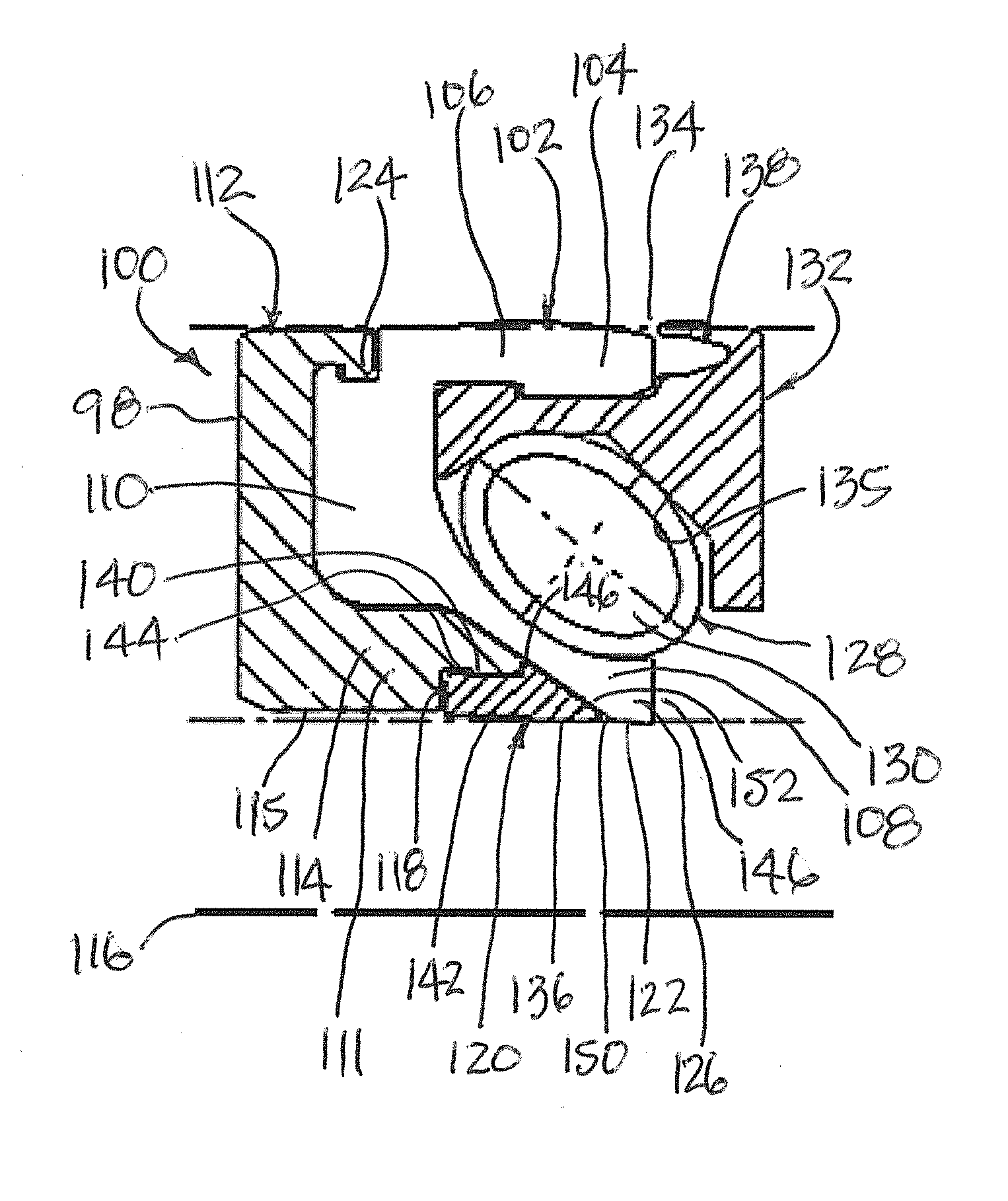
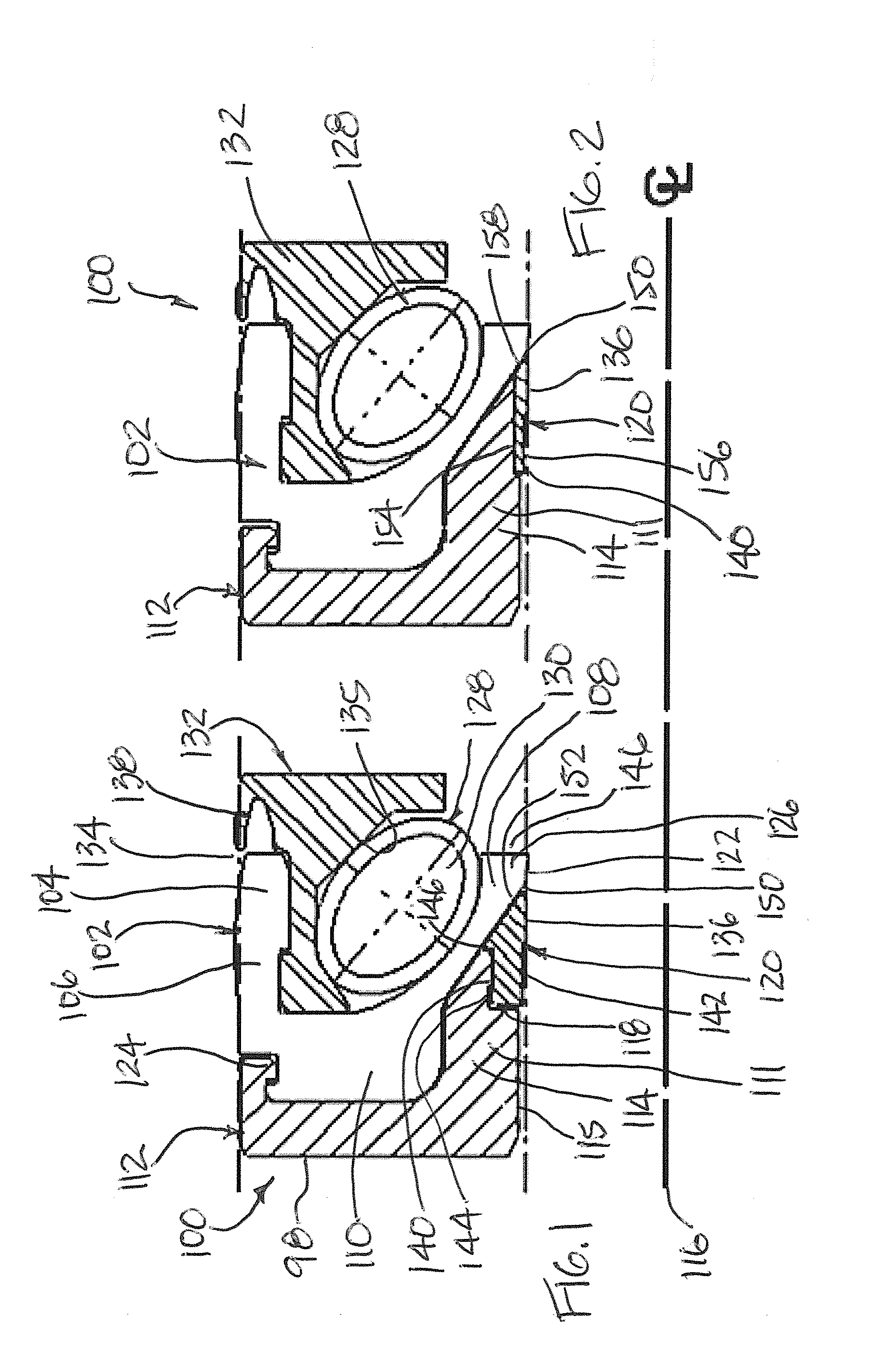
[0090]FIG. 1 shows a sealing assembly 100 comprising a sealing component 102 comprising...


PUM


Abstract

Sealing assemblies to provide sealing between a shaft and a housing comprising a sealing component comprising a body section as well as an outer flange and an inner flange both extending from said body section; a supporting component receiving said sealing component and comprising a relatively thick inner arm projecting into said sealing component and providing a supporting area spanning an inner portion of said body section and a portion of said inner flange; an anti-extrusion component engaged with said relatively thick inner arm; the minimum clearance between said anti-extrusion component and said shaft being less than the minimum clearance between said relatively thick inner arm and said shaft; said inner flange comprising a sealing area; wherein said sealing assembly is to be received in a cavity in said housing or on said shaft.

Description

FIELD[0001]The present invention generally relates to apparatus, system, and method involving sealing assemblies for dynamic applications especially suitable for but not limited to sealing fluids and gases in higher pressure applications and related methods.BACKGROUND[0002]Extrusion is a phenomenon in sealing technology that affects the life of a seal, especially in dynamic applications. In particular, the sealing part of the seal assembly, such as the elastic seal lip, can be extruded during service due to the high pressure application that the seal attempts to seal against. The higher the media pressure, shaft speed and temperature, the more critical the extrusion becomes, and thus the more important it is to minimize the extrusion gap, that is, the clearance that exists between the shaft and the supporting means receiving the seal body. There are applications wherein such supporting means is a sidewall of the cavity receiving the seal body. In other applications, particularly in ...

Claims


Application Information

Patent Timeline
IPC IPC(8): F16J15/32
CPCF16J15/3208F16J15/328F16J15/3204F16J15/166F16J15/3212F16J15/3236F16J15/324
Inventor DILMAGHANIAN, FARSHIDBALSELLS, PETER J.
Owner BAL SEAL ENG LLC
Why Eureka
Try Eureka