Combination of Impact Tool And Shaped Relatively Lower Modulus Material

a technology of impact tools and materials, applied in the field of impact tools, can solve the problems of metal tools with spalling, mushrooming and chipping, and disks that are not particularly useful in oscillating, and achieve the effects of reducing noise and vibration, improving interchangeable tool bits used, and low modulus inclusion

Inactive Publication Date: 2011-04-14
MCCARTY II H DOWNMAN +3
View PDF12 Cites 5 Cited by
  • Summary
  • Abstract
  • Description
  • Claims
  • Application Information

AI Technical Summary

Benefits of technology

[0002]The field of invention relates to impact tools, especially power impact tools, and more especially oscillating impact tools typically powered pneumatically or electrically, and insertion or inclusion of a parti...

Problems solved by technology

The power tool and hand tool industry, and the industry more broadly described as impacting tools, have been plagued by problems of metal to metal noise, and attendant vibration.
Further, metal tools have issues of spalling, mushrooming and chipping.
Unfortunate...

Method used


Image

  • Combination of Impact Tool And Shaped Relatively Lower Modulus Material
  • Combination of Impact Tool And Shaped Relatively Lower Modulus Material
  • Combination of Impact Tool And Shaped Relatively Lower Modulus Material

Examples


first example set

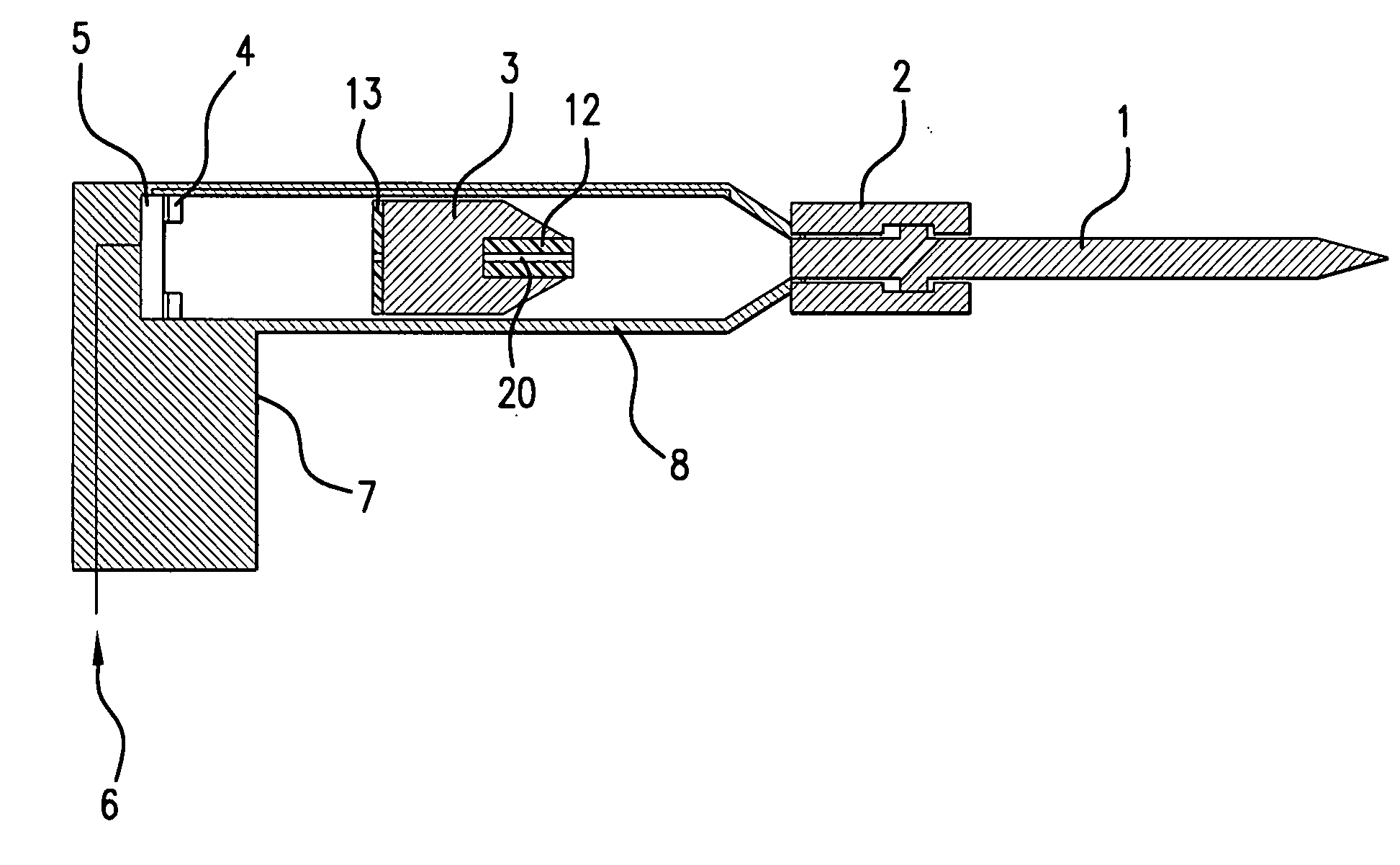
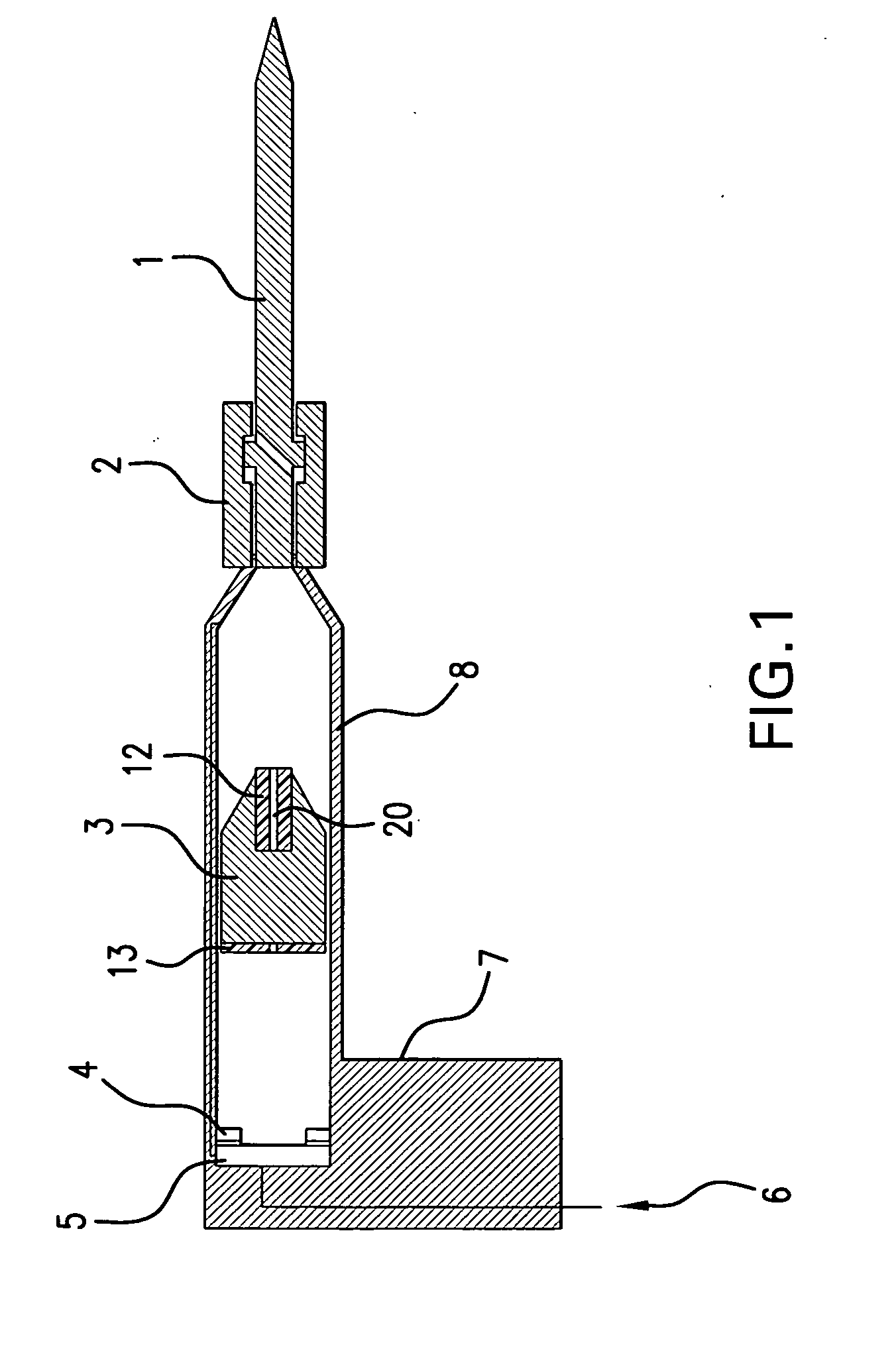
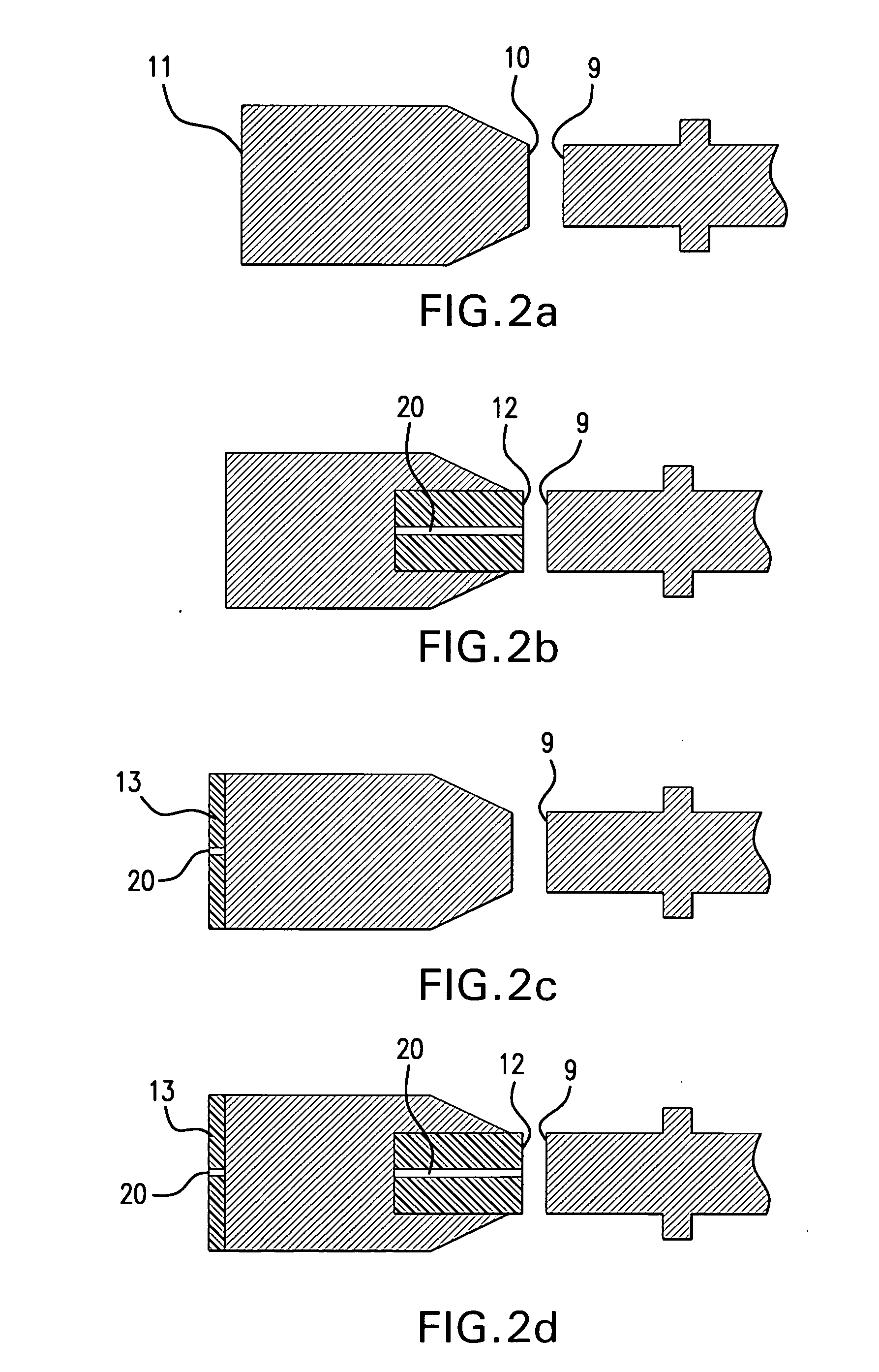
[0026]Table 1 shows an embodiment demonstrating the result an RLMI made of a simple high modulus polymeric material and the shape of the polymeric material. The first test, Test 1, utilized the simple placement of a flat cylindrical disk between the impacted end of a chisel and the impact end of a reciprocating piston. Test 2 utilized the placement of an RLMI made of high modulus polymeric material contained in a corresponding cylindrical cavity interior to the face of the impacting end of an oscillating or reciprocating piston which cylindrical impact end was slightly larger than the diameter of a chamfered tool. The impact of the piston was therefore transmitted from the impacting end of the piston (10) through the RLMI to the striking end of the tool (9) and thence to the working end of a chisel. In Test 3, the cutting tool chamfer on the impacted end was removed so that the diameter of the impacting and impacted surfaces match. (See FIG. 3). In all of the tests with the RLMI, th...

second example set

[0034]Table 2 shows the result of an embodiment of an RLMI made of a simple high modulus metal material of lower modulus than the adjacent metal without any modification of geometry, in this instance, using aluminum where the main tool material is steel. Two sets of tests were run with a conventional reciprocating piston and another with a hand-held tool.

[0035]Two tests were run on a test stand. The first configuration utilized the simple placement of a flat cylindrical disk between the impacted end of a chisel and the impact end of a conventional reciprocating piston. The second configuration utilized placement of an RLMI of lower modulus than the adjacent steel surfaces, namely aluminum, contained in a corresponding cylindrical cavity interior to the face of the impacting end of a reciprocating piston which cylinder was the diameter of a chamfered tool.

[0036]Two tests were run with a hand-held tool. As with the test stand, the first configuration utilized the simple placement of a...

third example set

[0044]Table 3 shows the result of an embodiment of a simple RLMI on the noise from a power tool. In this example, there were four configurations. Table 3 shows the results of an experiment in which an RLMI was added to a conventional power chisel on: the front, the back, and both sides of the piston.

[0045]More specifically, the first configuration was a control with no RLMI and the metal impacting end of an unmodified piston (16) hitting the impacted end of a cutting chisel. The second configuration was placement of a cylindrical insert of an RLMI in a cavity on the impacting end of the piston. The third configuration was placement of an RLMI cylindrical disk (15) on the back of the piston (11). The final and fourth configuration was placement of an RLMI cylindrical insert in a cavity on the impacting end of the piston and placement of an RLMI cylindrical disk on the back of the piston.

[0046]Test materials and test characteristics

[0047]Pneumatic chisel—Dayton Model 2Z486C Medium Air...


PUM

PropertyMeasurementUnit
Lengthaaaaaaaaaa
Lengthaaaaaaaaaa
Fractionaaaaaaaaaa

Abstract

An impacting tool, such as a jackhammer or electric hammer is proposed to be modified by a high modulus polymeric material, or metal of lower relative modulus than surrounding metal such as that of a piston. An interchangeable tool head is proposed to have inserted in a cavity in the impacted end such a high modulus polymeric material. Thus the term relatively lower modulus inclusion (“RLMI”) has been selected for the descriptive term. By using such relatively lower modulus material for an inclusion, which inclusion can be an insert, and modification of the piston or ram or impacting end of the tool, and additionally, if desired, the stop end of the piston or ram, the invention enables reduction of noise and vibration without substantially diminishing impact effectiveness and working time. Additionally, the working end of a cutting or impacting tool can be modified to a sharper angle because of diminished force through such relatively lower modulus inclusion. The edge angle, of for instance a chisel, may be modified to take advantage of mechanical changes resulting from the relatively lower modulus inclusion.

Description

CONTINUATION DATA[0001]For any application into national or regional stage for which this application can be continued (or its substantive equivalent) from an earlier application, and for PCT purposes, a continuation-in-part of U.S. Provisional Application 60 / 596,451 filed 23 Sep. 2005 bearing the name “Combination of Modified Impact Tool and Shaped Relatively Lower Modulus Material” and U.S. Provisional Application 60 / 597,367 filed on 28 Nov. 2005 entitled “Impact Tool With Relatively Lower Modulus Insert for Reducing Vibration and Noise.” Not for PCT purposes, but for purposes of the United States, in addition, to the extent permitted under continuation and continuation-in-part practice prior to issuance, the resulting utility application from this provisional application is a continuation in part of PCT / US02 / 23448 entitled “An Anti-Spalling Combination on an Impact Tool With an Improved Holding System” and entry into the U.S. national stage of PCT / US02 / 23448 filed in the United S...

Claims


Application Information

Patent Timeline
IPC IPC(8): B25D17/11B25D17/24
CPCB25D17/11B25D17/24B25D2222/61B25D2217/0023B25D2222/21B25D2217/0007
Inventor MCCARTY II, H. DOWNMANPOPPER, PETERGLANCEY, JAMES L.SCHUMM ILL, BROOKE
Owner MCCARTY II H DOWNMAN
Why Eureka
Try Eureka