Disk drive spindle motor with wire guide insert

a spindle motor and insert technology, applied in the direction of record information storage, record carrier contruction details, instruments, etc., can solve the problems of high labor intensity, insufficient motor volume, and high cost of split bearing spindle motor design, and achieve the effect of reducing labor intensity, reducing production costs, and increasing production costs

Inactive Publication Date: 2001-04-10
WESTERN DIGITAL TECH INC
View PDF8 Cites 63 Cited by
  • Summary
  • Abstract
  • Description
  • Claims
  • Application Information

AI Technical Summary

Problems solved by technology

Unfortunately, the top-down design may not provide sufficient motor volume to drive an elongated hub with multiple disks.
The split bearing spindle motor design is generally more expensive than a top-down spindle motor due, in part, to certain manufacturing issues.
The slot is normally formed by a machining operation and the stator wires are manually fed through the slot; the manual feeding of the stator wires through the slot is labor intensive and is therefore relatively expensive in terms of mass production.
Thus, if any difficulties are encountered in maintaining the stator wire within the gouged slot during assembly of the lower bearing to the shaft, the adhesive may not set properly, rendering the motor unusable.
Finally, imparting a slot into a high precision item such as the shaft may cause increased vibration of the shaft as a result of the slot decreasing the stiffness of the shaft.
Because the stator wires are quite thin and relatively flexible, it is likely difficult to thread the stator wires through the bore in an expedited fashion.
Additionally, due to space limitations between the stator and lower bearing upon final assembly, it would be difficult to feed the stator wires through the internal bore once the support ring has been secured to the shaft.

Method used


Image

  • Disk drive spindle motor with wire guide insert
  • Disk drive spindle motor with wire guide insert
  • Disk drive spindle motor with wire guide insert

Examples


Embodiment Construction

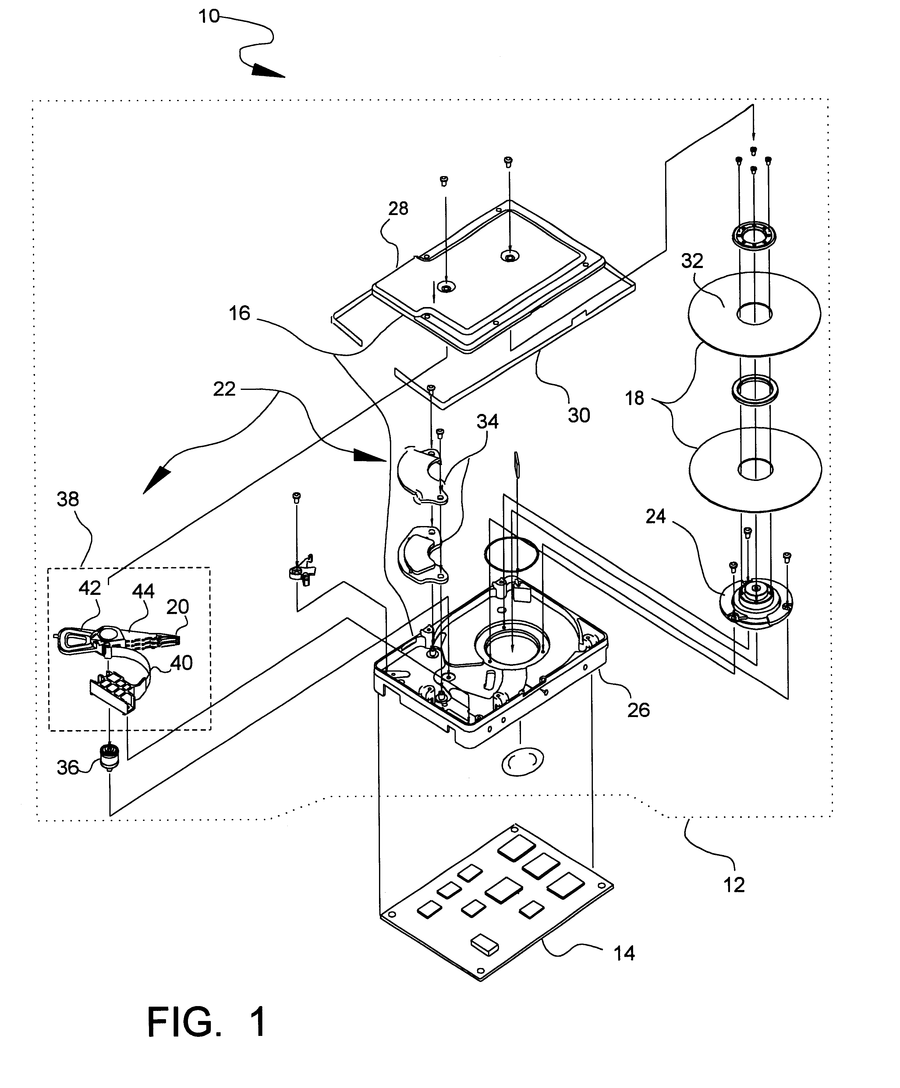
As shown in FIG. 1, a disk drive 10 embodying one preferred embodiment of the present invention includes a head disk assembly 12 and a printed circuit board assembly 14. The printed circuit board assembly 14 is suitably secured to an exterior of the head disk assembly 12 and controls operation of various components thereof.

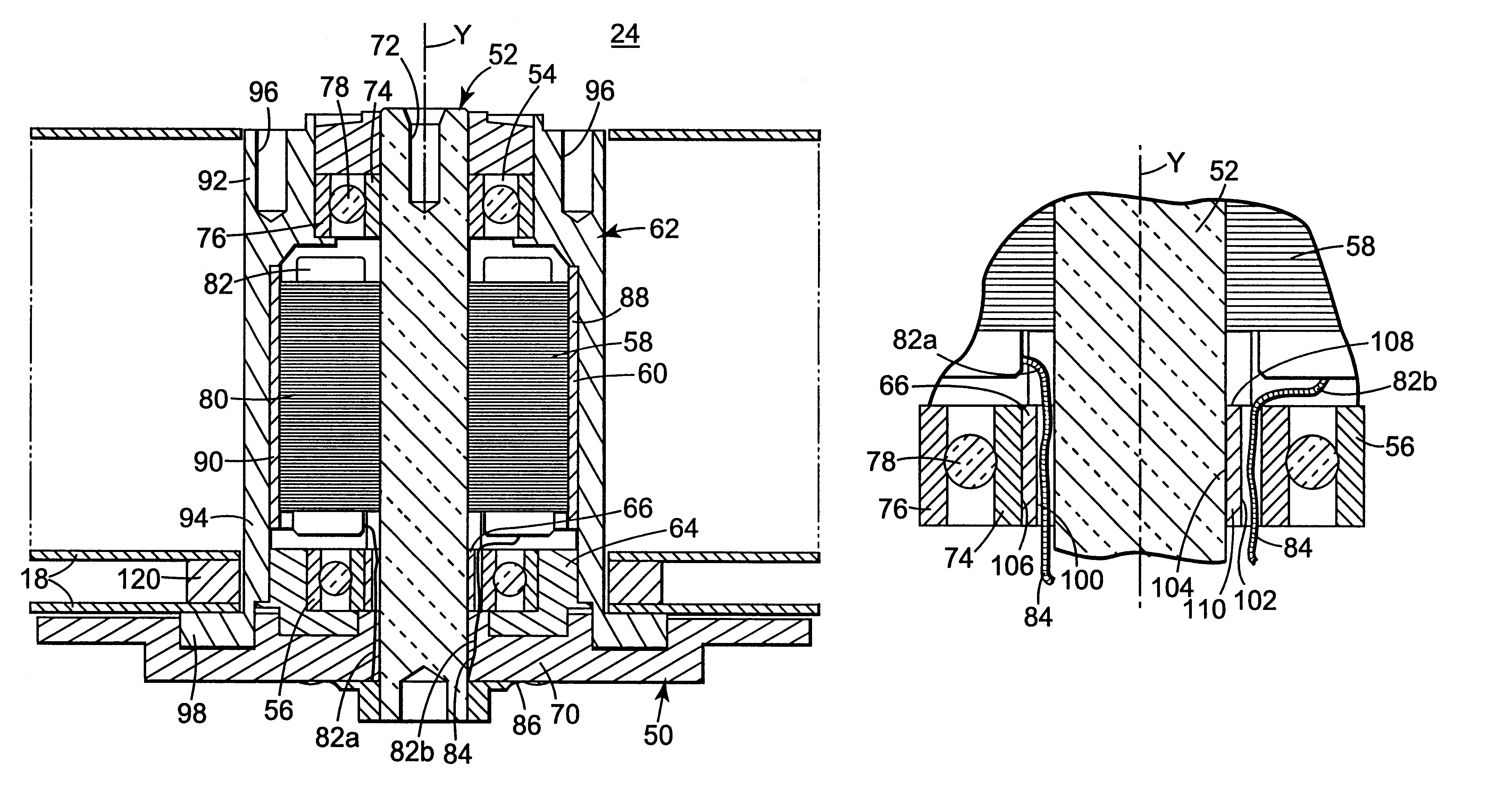
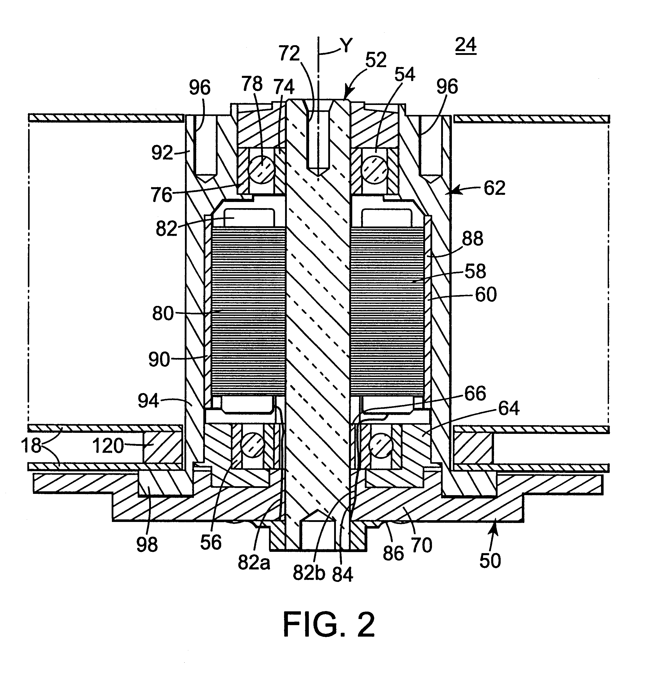
The head disk assembly 12 includes an enclosure 16, a magnetic disk 18, a magnetic transducer 20, a rotary actuator arrangement 22 and a spindle motor generally indicated at 24. As described in greater detail below, the magnetic disk 18, the magnetic transducer 20, the rotary actuator arrangement 22 and the spindle motor 24 are contained within the enclosure 16.

The enclosure 16 comprises a base 26 and a cover 28. The enclosure 16 is sealed to provide a relatively contaminant-free interior for remaining components of the head disk assembly 12. Suitably, a tape seal 30 is used to seal the enclosure 16.

The magnetic disk 18 and the magnetic transducer 20 are positione...


PUM

PropertyMeasurementUnit
diameteraaaaaaaaaa
outer diameteraaaaaaaaaa
inner diameteraaaaaaaaaa

Abstract

A spindle motor for a disk drive includes a shaft, an upper bearing, a lower bearing, a stator, a hub and wire guide body. The upper bearing surrounds the shaft. The lower bearing surrounds the shaft, is spaced-apart from the upper bearing, and includes an inner race. The stator surrounds the shaft between the upper bearing and the lower bearing, and includes a stator wire extending from a stator core. The hub is concentrically positioned about the stator. The wire guide body is secured between the shaft and the lower bearing, and includes a generally cylindrically shaped surface and a channel. The channel is sized to receive the stator wire and is formed adjacent to the cylindrically shaped surface such that the channel opens into at least one of the shaft and the inner race.

Description

1. Field of the InventionThe present invention relates to hard disk drives. More particularly, it relates to a disk drive spindle motor including a wire guide insert for facilitating rapid assembly at reduced costs.2. Description of the Prior Art and Related InformationA huge market exists for mass-market host computer systems such as servers, desktop computers, and laptop computers. To be competitive in this market, a hard disk drive must be relatively inexpensive and must accordingly embody a design that is adapted for low cost mass production. Numerous manufacturers compete in this expansive market and collectively conduct substantial research and development, at great annual cost, to design and develop innovative hard disk drives to meet increasingly demanding customer requirements.Each of the various contemporary mass-marketed hard disk drive models provides relatively large data storage capacity, often in excess of 1 gigabyte per drive. To this end, there exists substantial co...

Claims


Application Information

Patent Timeline
Patent Type & Authority Patents(United States)
IPC IPC(8): G11B19/20G11B25/04G11B33/12H02K5/173H02K5/22
CPCG11B19/2009G11B25/043G11B33/121H02K5/1737H02K5/225H02K2211/03
Inventor PHAN, BANGSASSINE, JOSEPH H.
Owner WESTERN DIGITAL TECH INC
Why Eureka
Try Eureka