Electronic power supply device

a technology of power supply device and electronic circuit, which is applied in the direction of power conversion system, sustainable manufacturing/processing, and efficient power electronics conversion, etc., can solve the problems of diodes and capacitors being damaged

Inactive Publication Date: 2001-04-17
STMICROELECTRONICS SRL
View PDF6 Cites 73 Cited by
  • Summary
  • Abstract
  • Description
  • Claims
  • Application Information

AI Technical Summary

Problems solved by technology

However, for the charging of the capacitors, there is a drawing of charging current which gives rise to a steep leading edge of the line current.
However, the resistor, in addition to attenuating low frequency harmonic contents, will limit the drawn current which, if excessively high, damages the diodes and the capacitors.

Method used


Image

  • Electronic power supply device
  • Electronic power supply device
  • Electronic power supply device

Examples


Embodiment Construction

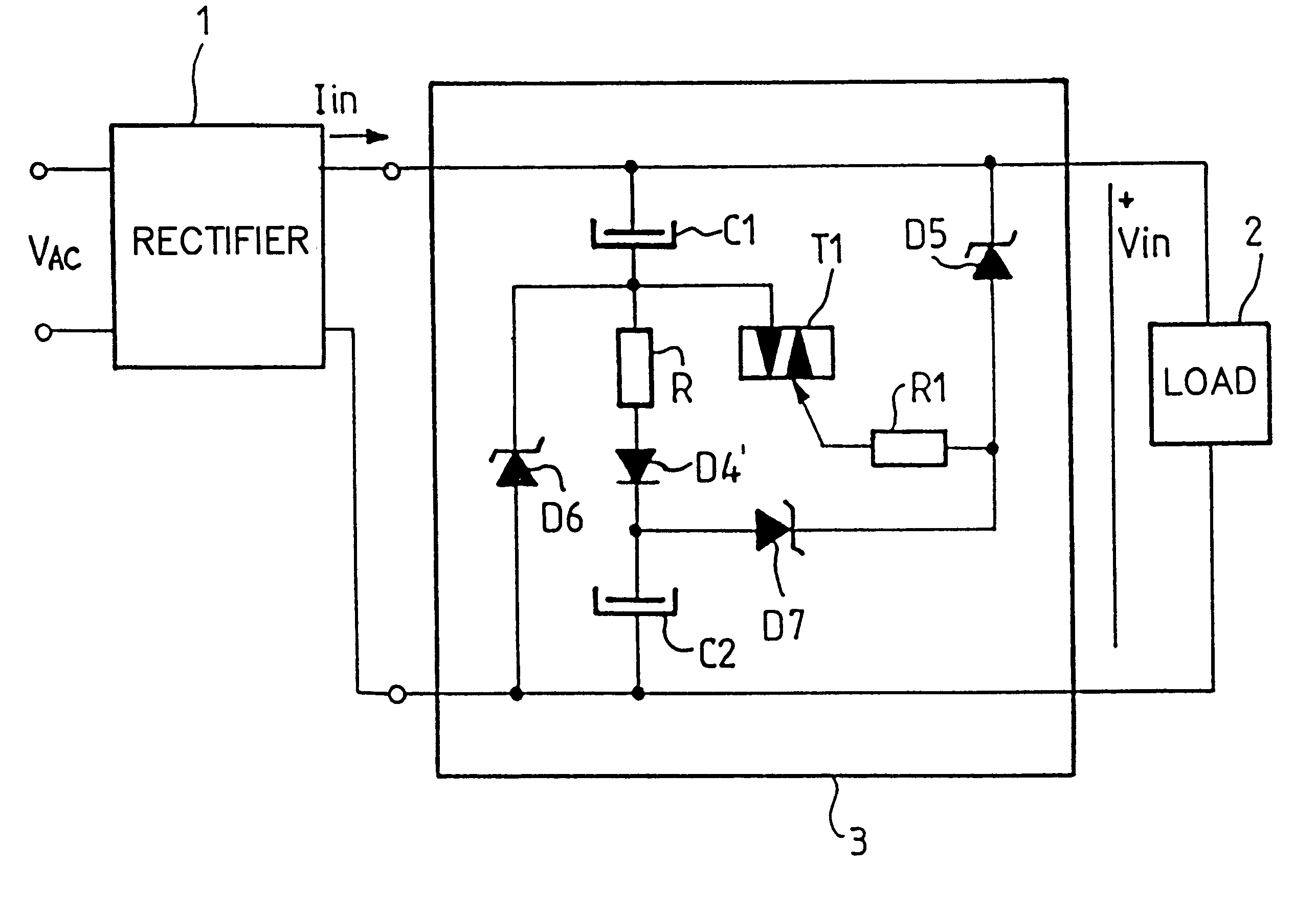
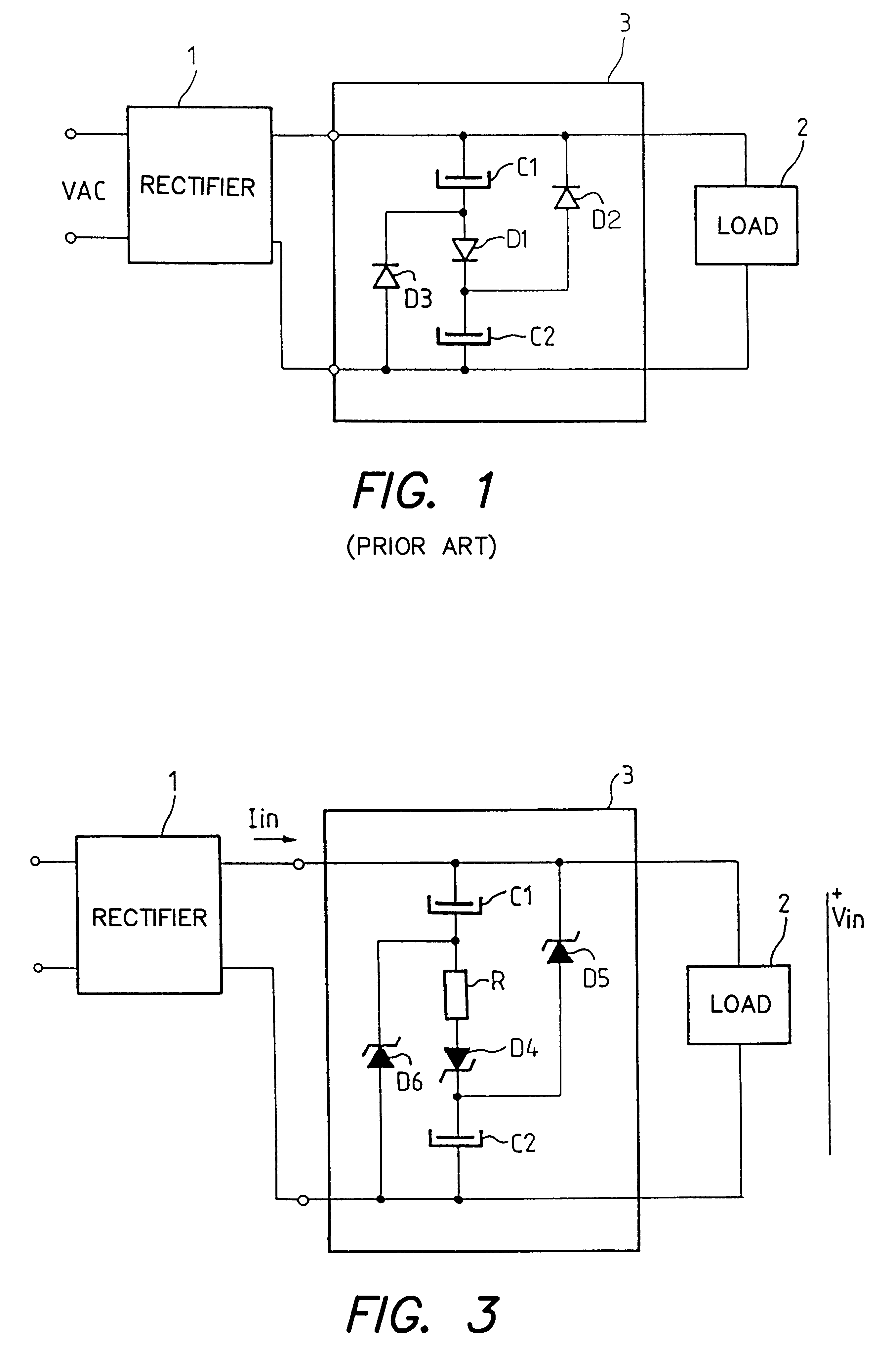
FIG. 3 shows a diagram of a power factor correction circuit 3 according to the invention, connected to a pair of output terminals of a bridge rectifier supplied by a mains voltage V.sub.AC.

The rectifier 1 and the power factor correction circuit 3 supply a load 2.

The circuit 3 has two filtering capacitors Cl and C2 series-connected with the output terminals of the rectifier 1. A resistor R and a first directly mounted diode D4 are series-connected between the two capacitors C1, C2.

A second diode D5 is reverse-connected and parallel-connected with the series-connected assembly formed by the first capacitor C1, the resistor R and the first diode D4.

A third diode D6 is reverse-connected and parallel-connected to the series-connected assembly of the second capacitor C2, the resistor R and the first diode D4.

The assembly formed by the resistor R and the first diode D4 controls the series charging of the capacitors C1 and C2. The resistor R according to the invention makes it possible to l...


PUM


Abstract

A power factor correction circuit using a first rectifier diode to control the series charging of two capacitors and two rectifier diodes to control the parallel discharging of the two capacitors. The power factor correction circuit further includes a resistor that is series-connected with the first diode to improve the power factor and to reduce the current drawn when the voltage is turned on. The rectifier diodes are advantageously voltage limiting diodes to protect the downline circuitry against overvoltages. In one improvement, a current-controlled electronic switch is used for protection against overvoltages that are just above the peak value of the line voltage.

Description

1. Field of the InventionThe invention relates to an electronic supply device. More particularly, it relates to a device with a power factor correction circuit.2. Description of the Prior ArtThere is a known circuit for the correction of power factor without line inductance. The circuit is connected to the output of a bridge rectifier and uses rectifier diodes for the series charging and parallel discharging of two filtering capacitors. An electrical diagram of such a circuit is shown in FIG. 1. A bridge rectifier 1 receives a periodically varying voltage V.sub.AC at a pair of input terminals. A power factor correction circuit 3 is connected between the rectifier 1 and a load 2 at a pair of output terminals of the rectifier. This circuit 3 uses two filtering capacitors, C1 and C2, having the same capacitance.A first rectifier diode D1 is connected directly between the two capacitors C1 and C2. The assembly is connected between two output terminals of the bridge rectifier.A second re...

Claims


Application Information

Patent Timeline
Patent Type & Authority Patents(United States)
IPC IPC(8): H02M1/00H02M1/32H02M1/42
CPCH02M1/32H02M1/4266Y02B70/123Y02B70/10Y02P80/10
Inventor WUIDART, LUC
Owner STMICROELECTRONICS SRL
Why Eureka
Try Eureka