
Trigger safety

a safety mechanism and trigger technology, applied in the direction of safety arrangement, weapon components, weapons, etc., can solve the problems of life or death, firearms will be incapable of firing, and the speed in which the safety can be disengaged may be a matter of life or death

Inactive Publication Date: 2001-05-01
FN MFG +1
View PDF25 Cites 31 Cited by
  • Summary
  • Abstract
  • Description
  • Claims
  • Application Information

AI Technical Summary

Benefits of technology

The simplicity of the design is another important advantage of the present invention. The manufacturing costs are significantly reduced as a result of the simplicity of the design. Since the safety does not interact with any internal components of the pistol, it is less likely to fail. Furthermore, unlike the safety mechanisms that disengage internal components not visible to the user, the user can see the operation of the present safety and know that it either will or will not prevent firing.

Problems solved by technology

Due to the potential risks of serious bodily injury or death, firearms must be handled carefully.
If the safety mechanism is engaged, the firearm will be incapable of firing, even if a round is in the chamber.
If the pistol is used in a military operation or by law enforcement, the speed in which the safety can be disengaged may be a matter of life or death.
While less critical, a hunter may also miss a clean shot if the safety cannot be disengaged quickly.
When the user is left-handed, a safety designed for right-handers will either be awkward or will need to be reversed to accommodate the left-hander.
Unfortunately, manipulation of an external safety that operates on internal components does not allow a user to verify that the pistol is actually incapable of firing without pulling the trigger.
Moreover, the safety's interaction with these internal components is subject to failure so that a pistol with the safety in the off position might not fire if the safety failed.

Method used


Image

  • Trigger safety
  • Trigger safety
  • Trigger safety

Examples


Embodiment Construction

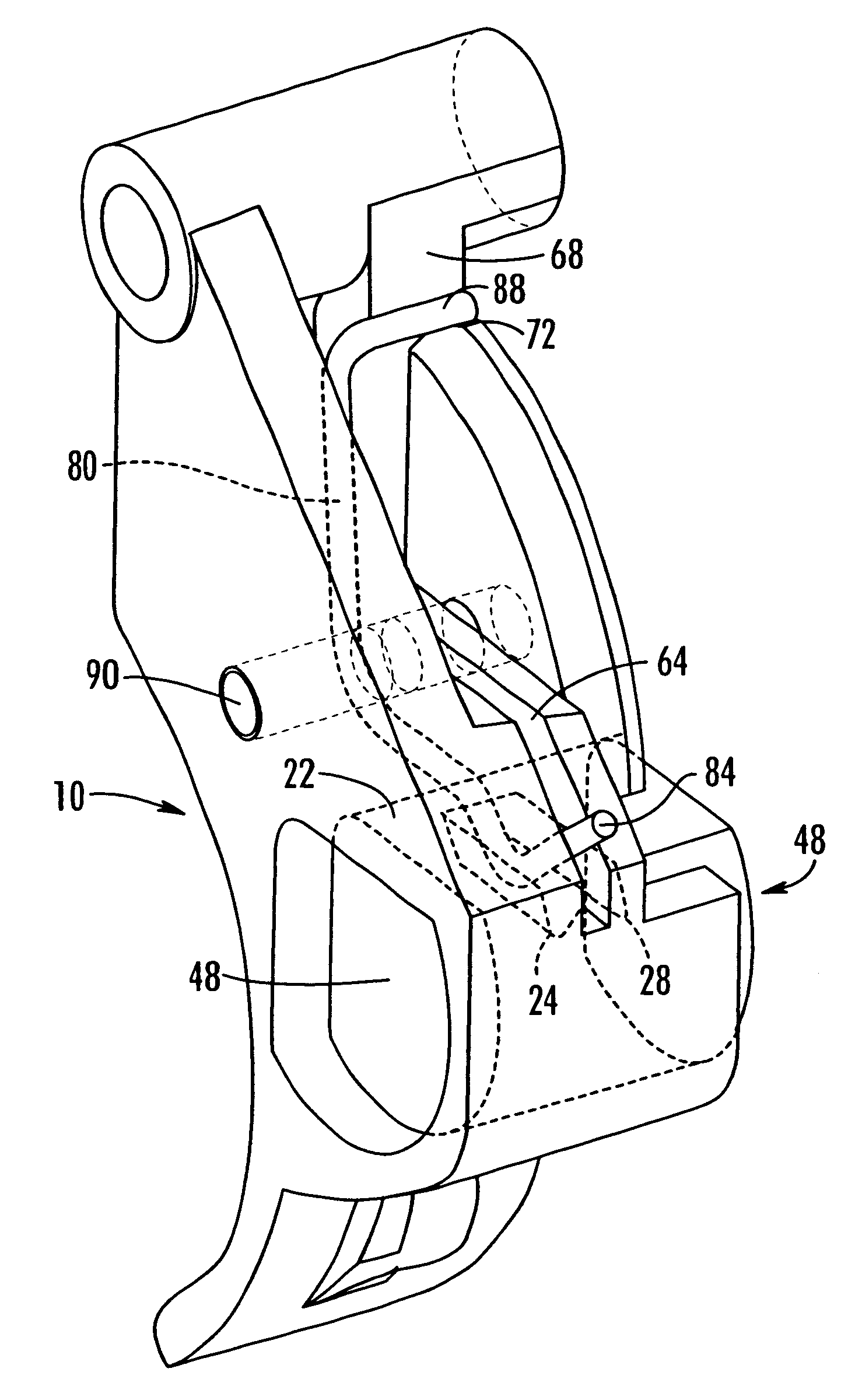
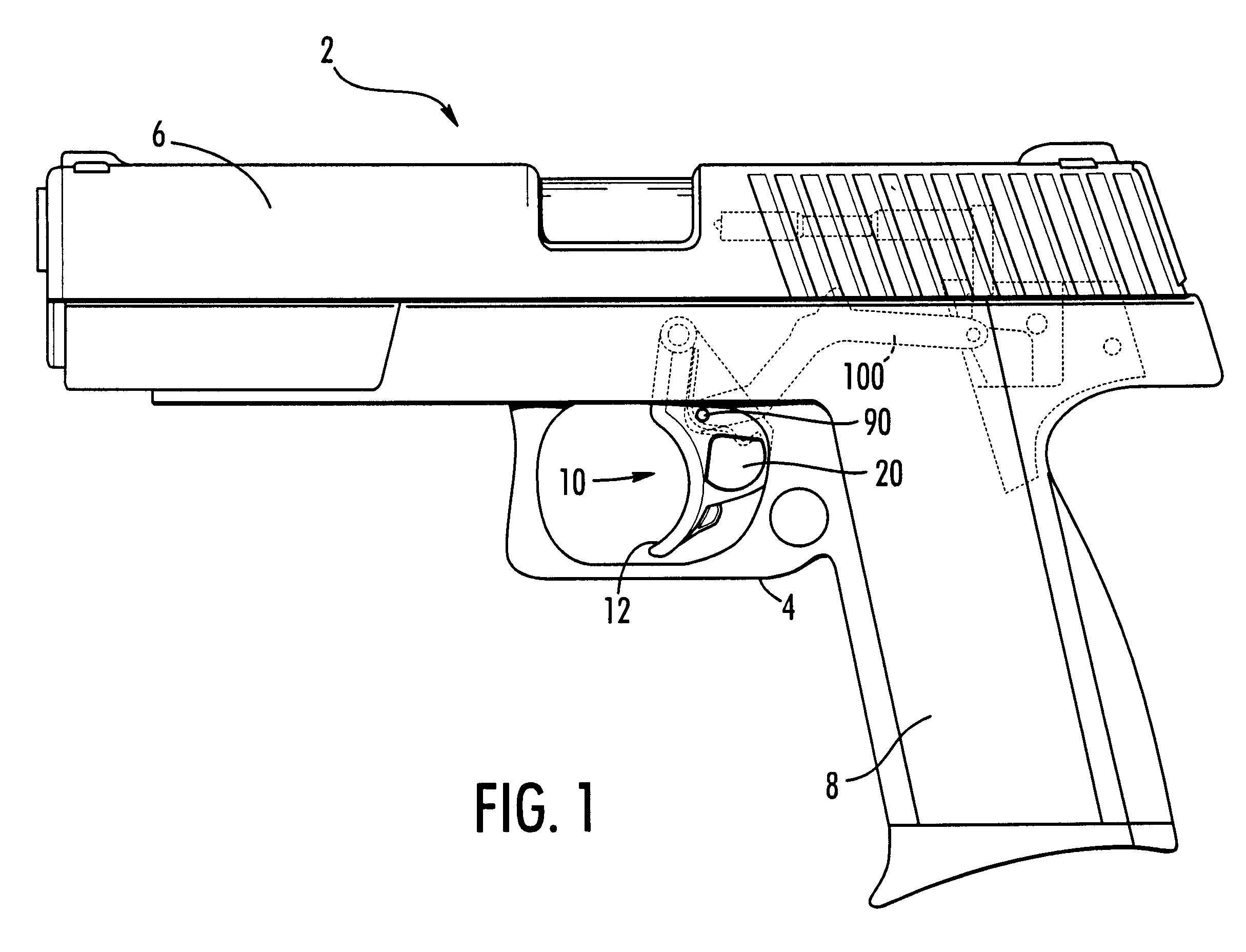
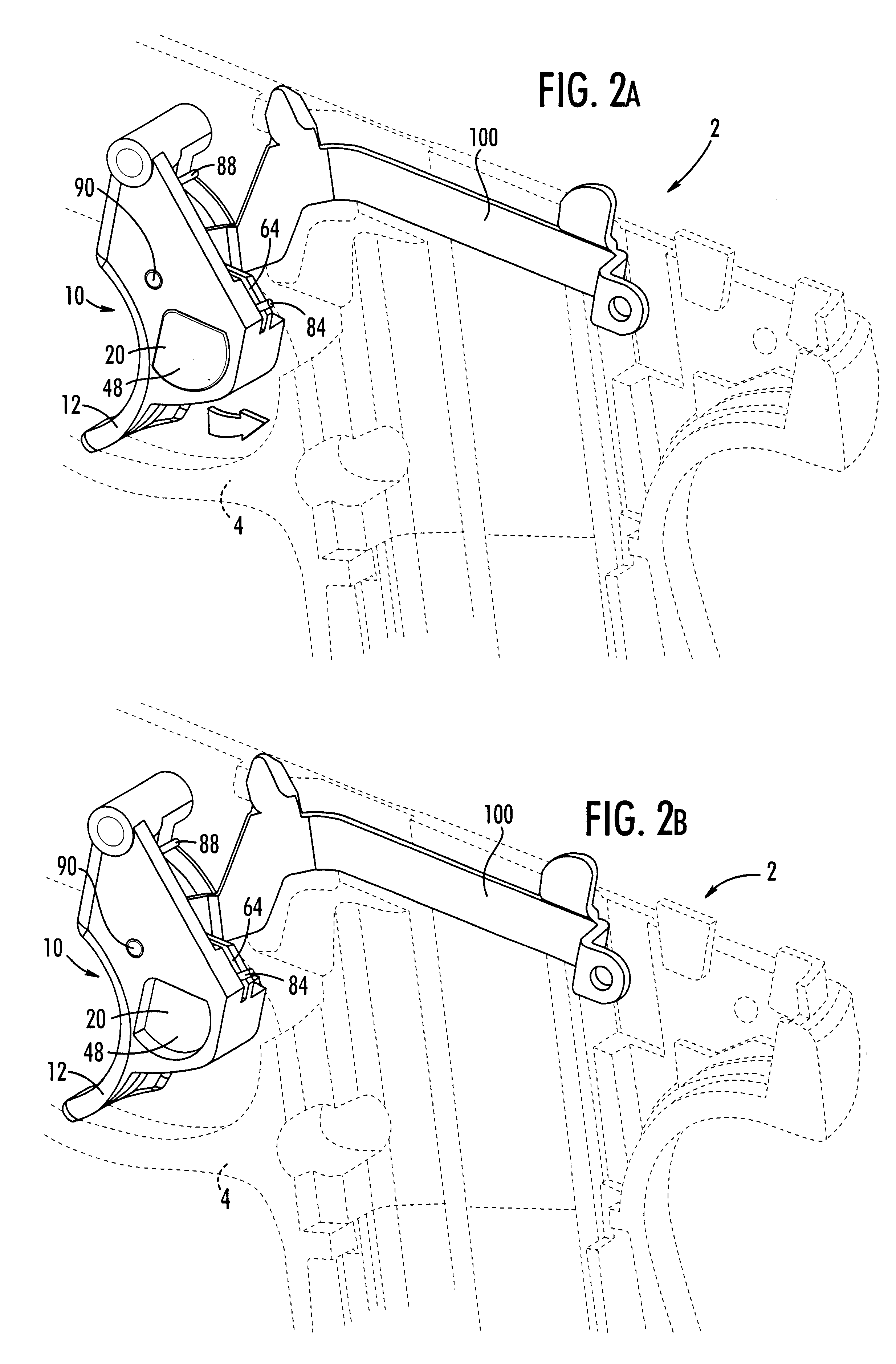
Referring now to the figures, the present invention is a trigger safety for a pistol. The safety, generally referred to by reference number 10, comprises a trigger 12 having a plug 20 slidably received therein so that plug 20 can be moved laterally between a fire position that allows movement of trigger as illustrated in FIG. 2A and a safe position that prevents movement of trigger as illustrated in FIG. 2B. The term "laterally" means orthogonal to the direction trigger 12 is moved to fire pistol 2. In a safe position, plug 20 laterally extends outside the trigger envelope so that the movement of trigger 12 is blocked by the engagement of plug 20 with the frame 4 of the pistol 2; however, in a fire position, plug 20 is within trigger envelope so that trigger 12 is capable of firing pistol 2. By the term envelope, it is meant the maximum cross sectional area defined by the outermost surface of trigger when viewed from the front of the firearm. Plug 20 is within the envelope when plug...


PUM


Abstract

A trigger safety for a pistol includes a laterally slidable plug incorporated into the trigger that, when slid laterally to extend beyond the confines of the trigger, will prevent rearward movement of the trigger by the plug's interference with the pistol frame. A spring internal to the trigger, imparts a force on plug to retain it positioned in either the safety position or the fire position and resist movement. The plug can be reversed for left-handed users so that the pistol can be placed in a "safe" or a "fire" position with the trigger finger of either hand.

Description

1. Field of the InventionThe present invention relates to safety mechanisms for firearms and particularly to a trigger safety mechanism.2. Discussion of BackgroundDue to the potential risks of serious bodily injury or death, firearms must be handled carefully. Each year, numerous people die from the accidental discharge of a firearm. In order to prevent accidental discharge, all firearms come equipped with at least one safety mechanism. If the safety mechanism is engaged, the firearm will be incapable of firing, even if a round is in the chamber.Although safeties play an important role in preventing accidental discharge of a pistol, a safety must sometimes be capable of quick disengagement. If the pistol is used in a military operation or by law enforcement, the speed in which the safety can be disengaged may be a matter of life or death. While less critical, a hunter may also miss a clean shot if the safety cannot be disengaged quickly.Often safety mechanisms will be located on eit...

Claims


Application Information

Patent Timeline
Patent Type & Authority Patents(United States)
IPC IPC(8): F41A17/46F41A17/00
CPCF41A17/46
Inventor SCHMITTER, EDWARD P.PRISOVSKY, ZDENEKSNIEZAK, GARY A.SPANIEL, FRANK A.
Owner FN MFG
Learn More