Drilling tool

a drilling tool and tool body technology, applied in the field of drilling tools, can solve the problems of reducing affecting the work efficiency of the drill bit,

Inactive Publication Date: 2001-05-29
MITSUBISHI MATERIALS CORP +1
View PDF9 Cites 37 Cited by
  • Summary
  • Abstract
  • Description
  • Claims
  • Application Information

AI Technical Summary

Problems solved by technology

These burrs make it impossible, for example, to obtain an appropriate clamping force when clamping the metal plate with bolts, rivets or the like.
This burr removing operation requires a lot of effort and time.
In this drilling tool endowed with such a burr removing function, the burr removing tip can protrude and retract, so that the abutment of the cutting edge at the time of burr removing operation is unstable, and the sharpness of the cutting edge slightly deteriorates, resulting in a degeneration of the burr removing function.
Thus, the tip cannot be replaced easily.
Further, since three holding walls are thus formed in the cartridge, an increase in the size of the cartridge is inevitable.
However, in the drilling tool described in this publication, the portion of the holding portion of the cartridge holding the side surface positioned at the tool main body rear end of the burr removing tip is formed by the forward end edge of the strip like member forming the cartridge, so that, in this portion, the side surface of the burr removing tip is simply supported in line contact, and there is a danger of the mounting stability of the burr removing tip being impaired.
In particular, this portion holding the side surface positioned at the tool main bo...

Method used


Image

  • Drilling tool
  • Drilling tool
  • Drilling tool

Examples


first embodiment

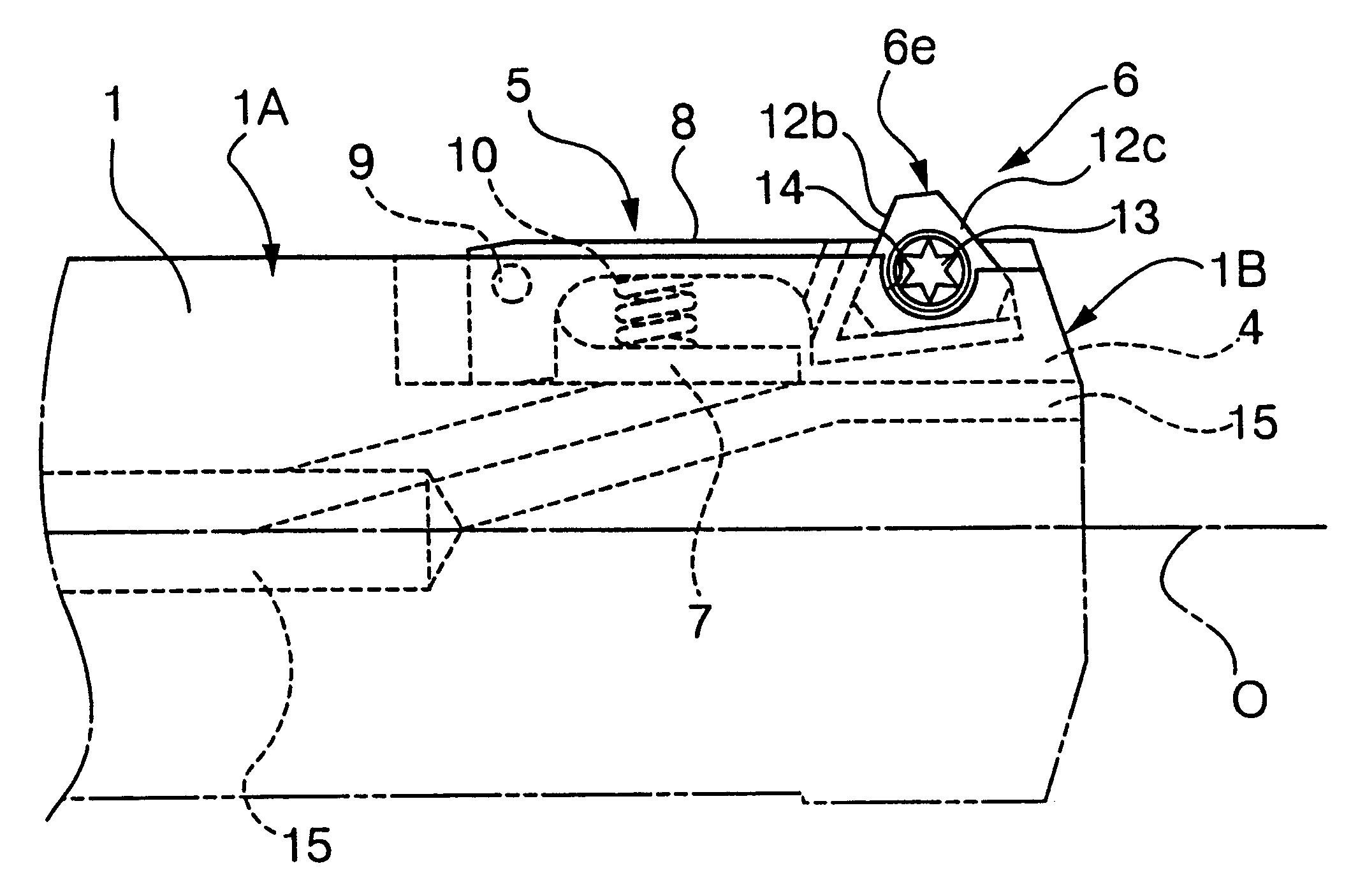
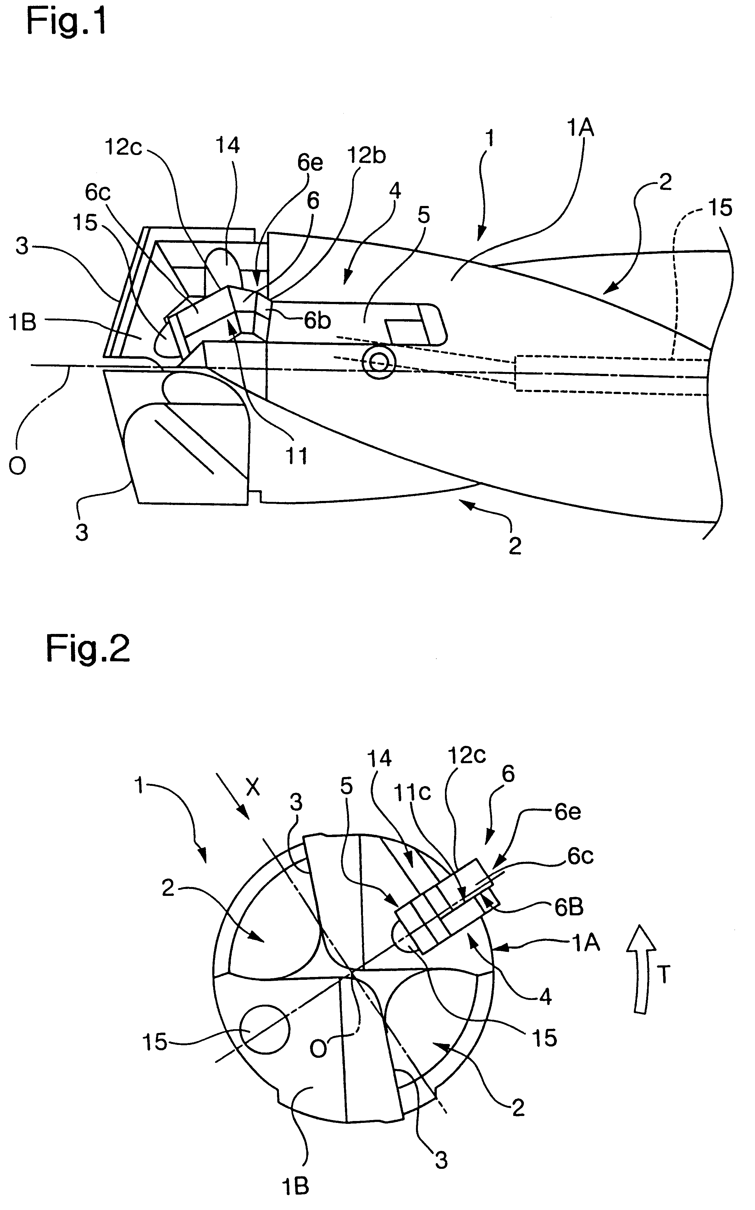
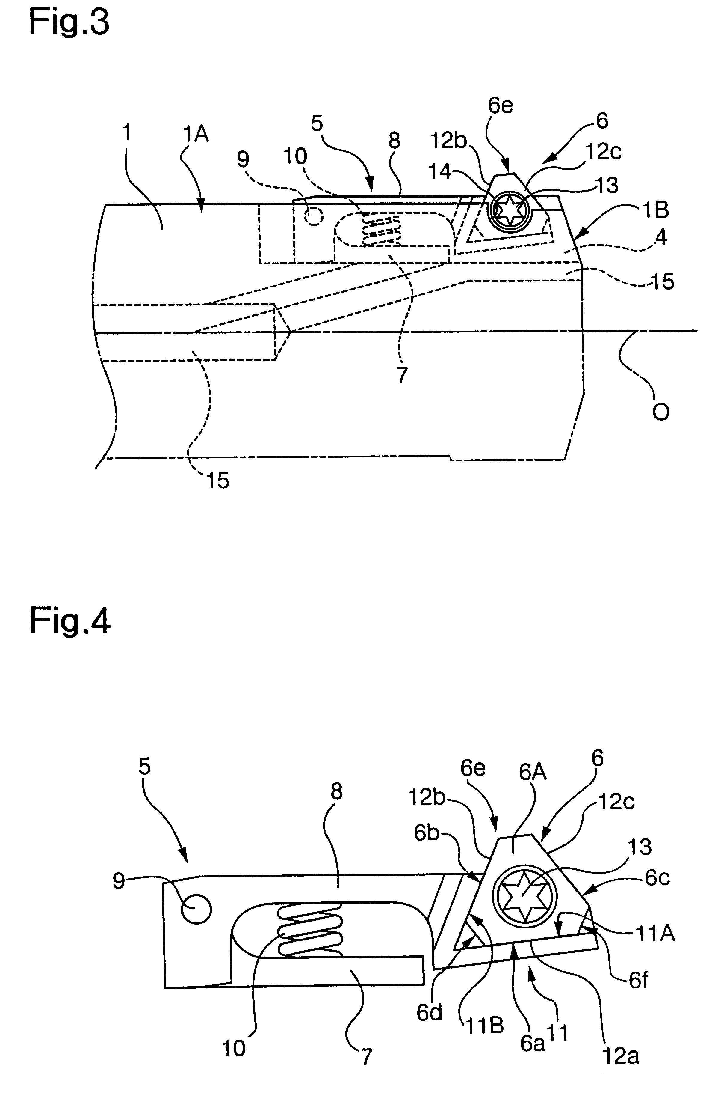
FIGS. 1 through 4 show the present invention. In this embodiment, the forward end portion of the tool main body 1 is substantially cylindrical, and, on the outer peripheral surface 1A of this forward end portion, there are formed a pair of chip discharge grooves 2 twisted from the forward end surface 1B to the rear end toward the rear side of the tool rotating direction T. In the forward end portion of the wall surface of these chip discharge grooves 2, cutting edge tips are joined to provide cutting edges 3. In the outer peripheral surface 1A of one of the lands defined between the chip discharge grooves 2 in the circumferential direction of the tool main body 1, there is formed a groove 4 open at the forward end surface 1B of the tool main body 11 and extending along the axis O of the tool main body 1. This groove 4 accommodates a cartridge 5, and a burr removing tip 6 is detachably attached to the forward end portion of this cartridge 5.

Here, as shown in FIG. 4, the cartridge 5 i...

second embodiment

In the drilling tool of the second embodiment in which the groove 21 is formed so as not to be open at the forward end surface 1B of the tool main body 1, the forward end surface 1B of the tool main body 1 is not cut away by the groove on the rear side of the tool rotating direction T of the cutting edge 3, so that it is possible to improve the rigidity of the tool, and, regarding the large load applied to the cutting edge 3 at the time of drilling, it is possible to prevent breakage from occurring to the tool main body 1. Further, since the groove 21 is not open at the forward end surface 1B, the chips generated by the cutting edges 3 do not enter the groove 21, and there is no danger of the operation of the cartridge 5 being hindered by the intrusion of the chips to make it impossible for the burr removing tip 6 to protrude and retract smoothly.

third embodiment

Next, FIGS. 8 through 12 show the present invention. In this embodiment, the outer configuration of the tool main body 31 is substantially cylindrical, and, in the outer periphery of the forward end portion thereof, there are formed a pair of chip discharge grooves 32 which are twisted rearward in the tool rotating direction T they extend toward the rear end of the tool along the axis O and which are open at the forward end surface 33 of the tool main body 31 to extend to the rear end, and, to the forward ends of the wall surfaces of these chip discharge grooves 32, cutting edge tips 34 formed of a hard material such as hard metal are attached by brazing, and cutting edges 35 for forming a hole in the workpiece are formed at the forward ends of these cutting edge tips 34. In the tool main body 31, a supply hole for cutting fluid are formed so as to extend from the rear end of the tool toward the forward end along the axis O. This supply hole 36 is branched into two portions at the f...


PUM

PropertyMeasurementUnit
Shapeaaaaaaaaaa
Deformation enthalpyaaaaaaaaaa
Displacementaaaaaaaaaa

Abstract

A drilling tool includes a tool main body having a cutting edge at its forward end, a groove provided in the outer peripheral surface provided at the forward end of the tool main body, a cartridge accommodated in the groove and capable of elastic deformation in a radial direction of the tool main body, and a burr removing tip in the form of a substantially triangular flat plate detachably mounted to the cartridge and capable of protruding from and retracting into the outer peripheral surface of the tool main body. The cartridge is equipped with two holding walls which are in face contact with the two side surfaces of the three side surfaces corresponding to the three sides of the triangle formed by the burr removing tip. The two side surfaces of the burr removing tip are in face contact with the two holding walls, and the remaining one side surface is mounted to the cartridge in an open state.

Description

1. Field of the InventionThe present invention relates to a drilling tool endowed with a burr removing function which makes it possible to remove burrs as they are generated on the obverse and reverse sides of a metal plate such as a steel plate, copper plate or aluminum plate when drilling a hole in it.2. Description of the Related ArtWhen drilling a hole in a metal plate such as a steel plate with a drilling tool such as a drill, burrs may be generated on the obverse and reverse sides of the metal plate. These burrs make it impossible, for example, to obtain an appropriate clamping force when clamping the metal plate with bolts, rivets or the like. In view of this, a post-processing operation for removing burrs is conventionally performed by using a grinding tool such as a grinder. This burr removing operation requires a lot of effort and time.To solve this problem, a drilling tool endowed with a burr removing function making it possible to remove burrs as they are generated on th...

Claims


Application Information

Patent Timeline
IPC IPC(8): B23B51/10B23B51/02
CPCB23B51/02B23B51/101B23B2251/50B23B2260/136Y10T408/8583Y10S408/714Y10T408/906Y10T407/134Y10S408/713
Inventor YAMADA, JUNMIURA, KAZUMASA
Owner MITSUBISHI MATERIALS CORP
Why Eureka
Try Eureka