Smoke detector

a detector and smoke technology, applied in the field of smoke detectors, can solve the problems of small proportion of scattered radiation hitting the radiation receiver, and the loss of remaining scattered radiation to measuremen

Inactive Publication Date: 2001-05-29
ROBERT BOSCH GMBH
View PDF3 Cites 23 Cited by
  • Summary
  • Abstract
  • Description
  • Claims
  • Application Information

AI Technical Summary

Problems solved by technology

A disadvantage of each of the known methods is that only a small proportion of the scattered radiat

Method used


Image

  • Smoke detector
  • Smoke detector
  • Smoke detector

Examples


Embodiment Construction

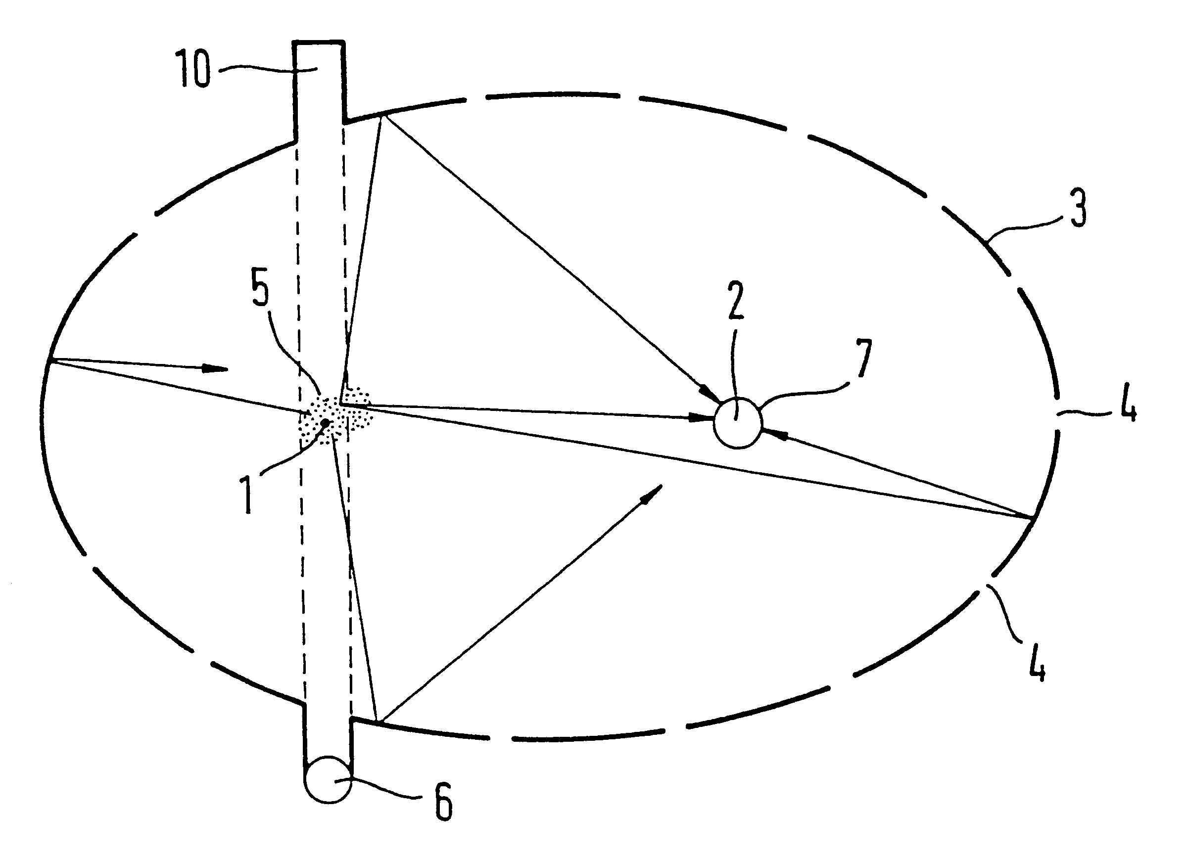
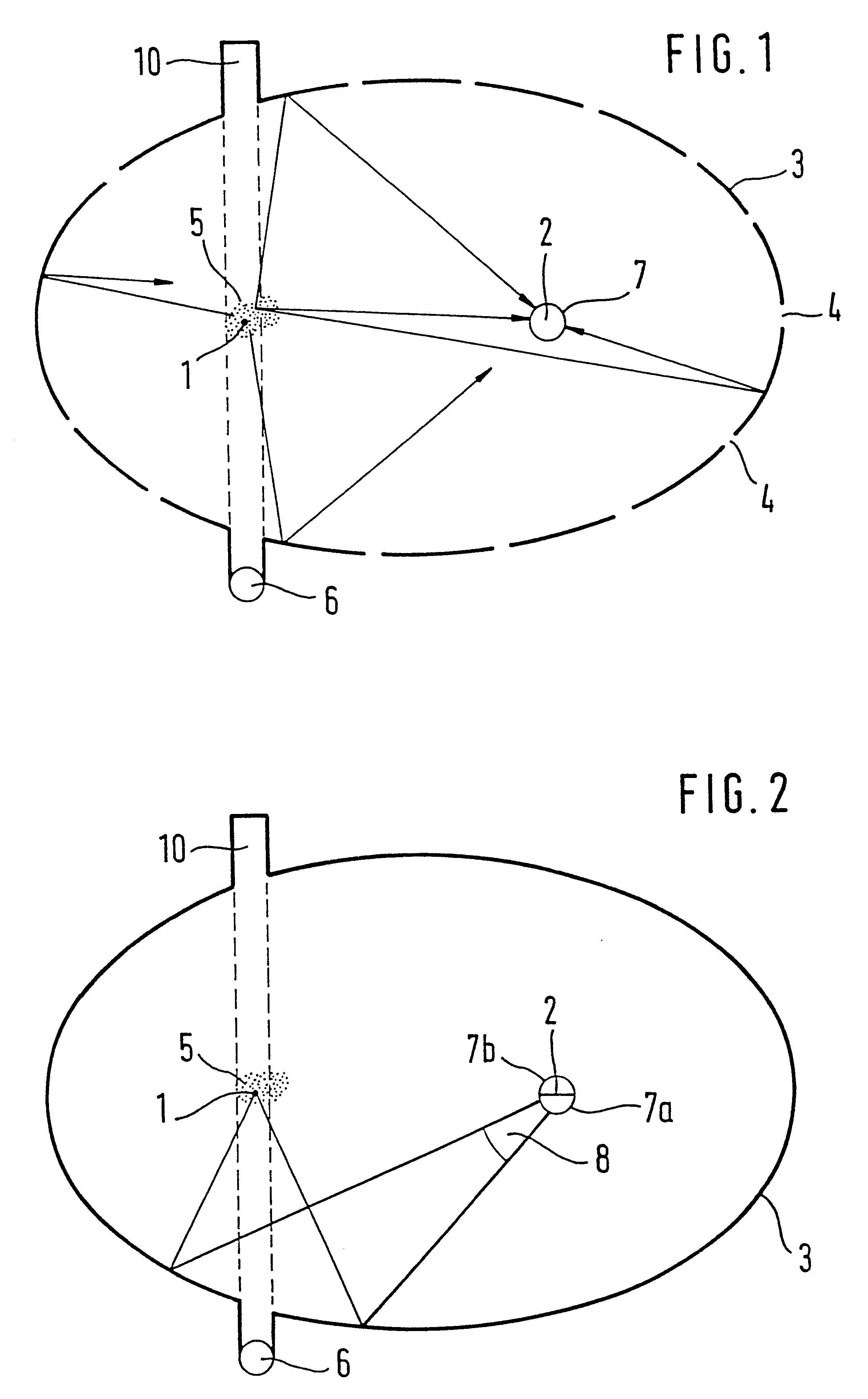
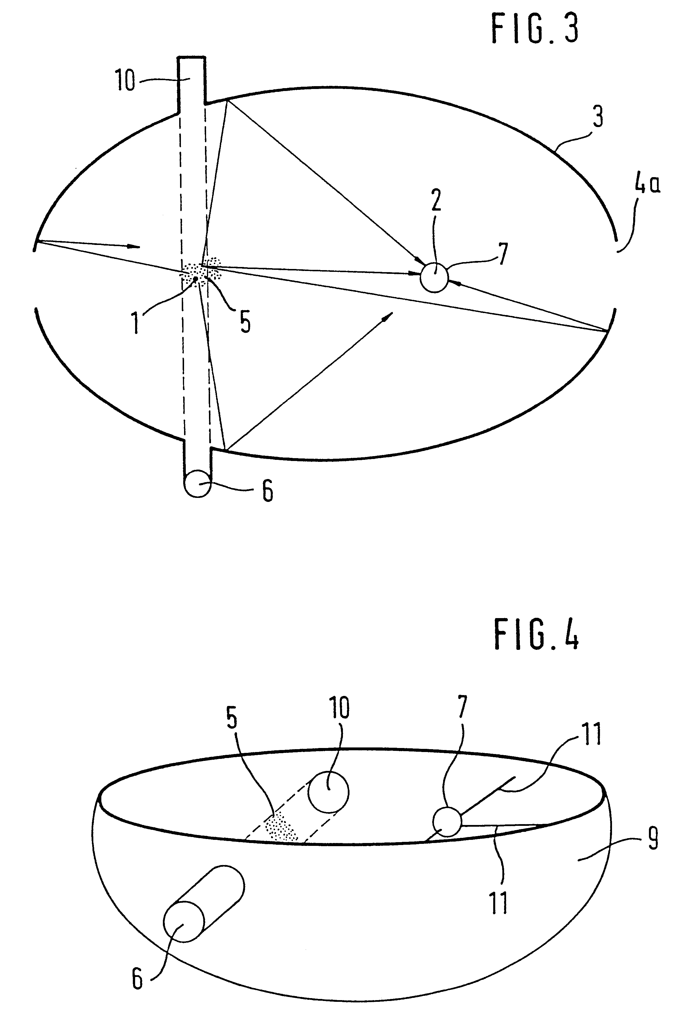
FIG. 1 shows the basic arrangement in a section taken through the focal points 1 and 2 of a hollow ellipsoid 3. The hollow ellipsoid 3 is mirror-coated on the inside and is provided with openings 4, which are small in proportion to the inside surface area of the hollow ellipsoid 3, or in other words make up a maximum of 10% of the inside surface area, for example. The first focal point one and its immediate vicinity form the measuring field 5, where smoke particles can be simultaneously irradiated by a radiation transmitter 6 and detected by a radiation receiver 7 at the focal point 2. The radiation receiver 7 includes a radiation collector, which is mounted at the second focal point 2. However, it is also possible instead for the radiation receiver itself to be mounted there. As the radiation collector, it is possible for instance for one hemispherical lens each to be used for the half shell of the hollow ellipsoid 3 located below and above the plane of the drawing, respectively.

Th...


PUM


Abstract

A smoke alarm on the scattered radiation principle. Having a measuring field (5), accessible to smoke particles, in a measuring chamber, at which field the radiation direction of a radiation transmitter (6) is aimed, and scattered radiation occurring in the measuring field (5) can be received by a radiation receiver (7); the measuring chamber includes a portion of the hollow ellipsoid (3) which is mirror-coated on the inside; the measuring field (5) is disposed at the first focal point (1) of the hollow ellipsoid; the radiation receiver (7) is disposed at the second focal point (2) of the hollow ellipsoid (3).

Description

PRIOR ARTThe invention is based on the generic type defined by the preamble to independent claim 1.For detecting fires early, smoke alarms are generally used. One method of detecting smoke particles is to measure radiation scattered at smoke particles. Such smoke alarms based on the scattered radiation principle typically employ the method of forward scattering, because with it larger signals can be attained at the radiation receiver. Such a smoke alarm comprises a radiation transmitter (normally pulsed), a lens for focusing the rays, and a radiation receiver, for instance a photo diode, optionally with a lens for capturing the scattered radiation. Radiation receivers and radiation transmitters have no direct visual communication but instead are optically separated from one another by suitable mechanical provisions. There is an obtuse angle between the direction of radiation transmission and the direction of reception, and the scattering angle at the smoke particles to be detected i...

Claims


Application Information

Patent Timeline
IPC IPC(8): G08B17/107G08B17/103G01N21/53
CPCG08B17/107G08B17/113
Inventor OPPELT, ULRICH
Owner ROBERT BOSCH GMBH
Why Eureka
Try Eureka