Method and apparatus for holding a capacitor without separable fasteners

a technology of separable fasteners and capacitors, which is applied in the field of mounting brackets, can solve the problems of saving assembly time and manufacturing costs, and achieve the effects of reducing the likelihood of explosion, reducing assembly time, and saving manufacturing costs

Inactive Publication Date: 2001-06-12
MAGNETEK
View PDF19 Cites 24 Cited by
  • Summary
  • Abstract
  • Description
  • Claims
  • Application Information

AI Technical Summary

Benefits of technology

A further object of the invention is to provide a capacitor holder which reduce the time to assemble to the fixture, and thus saves manufacturing costs.
Another object of this invention is to provide a device which reduces the likelihood of explosion due to improper capacitor orientation.
Yet another object is to provide a capacitor holder which guarantees a polarity match.

Problems solved by technology

Specifically, it accomplishes the mounting of the capacitor without the use of separable fasteners, thus saving assembly time and manufacturing costs.

Method used


Image

  • Method and apparatus for holding a capacitor without separable fasteners
  • Method and apparatus for holding a capacitor without separable fasteners
  • Method and apparatus for holding a capacitor without separable fasteners

Examples


Embodiment Construction

The applicants' invention will be best understood when considered in light of the following description of the preferred embodiments of the invention, as illustrated in the attached drawings wherein like reference numerals and characters refer to like parts.

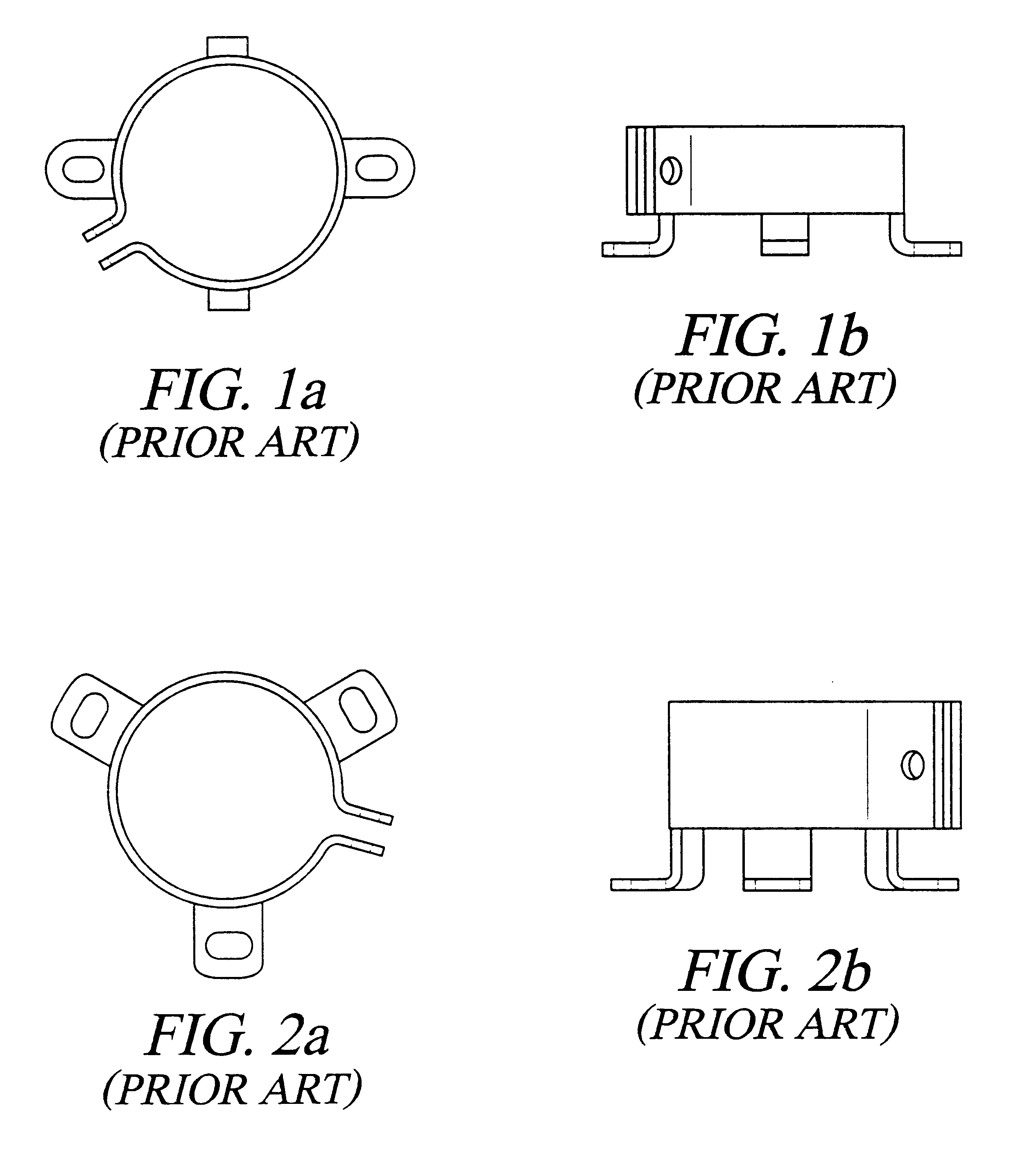
FIGS. 1a and 1b show a prior art clamp bracket used to mount capacitors in a panel. The clamp bracket requires screw and nut fasteners. FIGS. 2a and 2b show a similar clamp mounting bracket using more screw and nut fasteners than the mounting bracket shown in FIGS. 1a and 1b. Due to the multiplicity of fasteners required to mount a single capacitor, the assembling time increases dramatically as the number of capacitors to be installed in an electronic assembly increase.

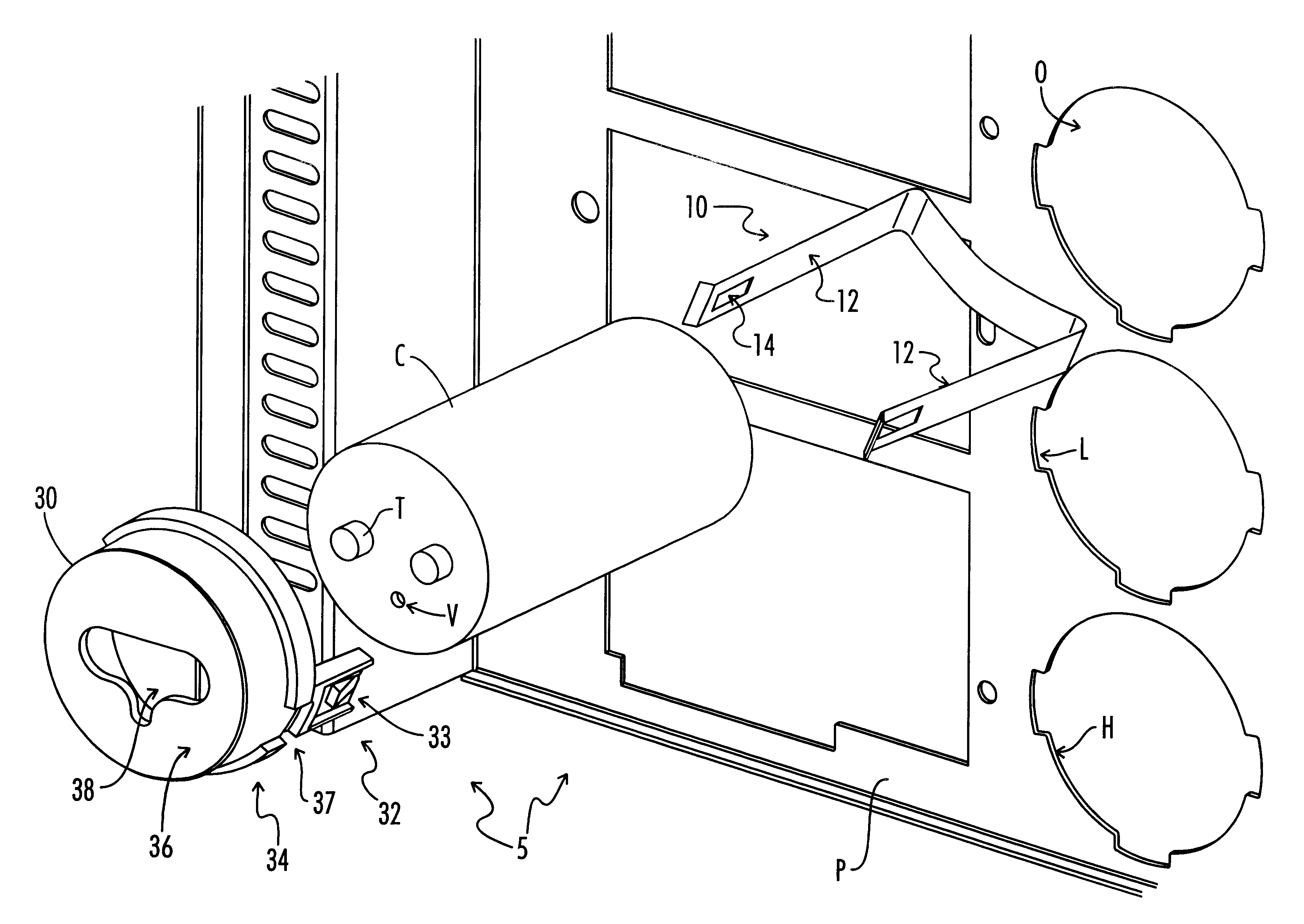
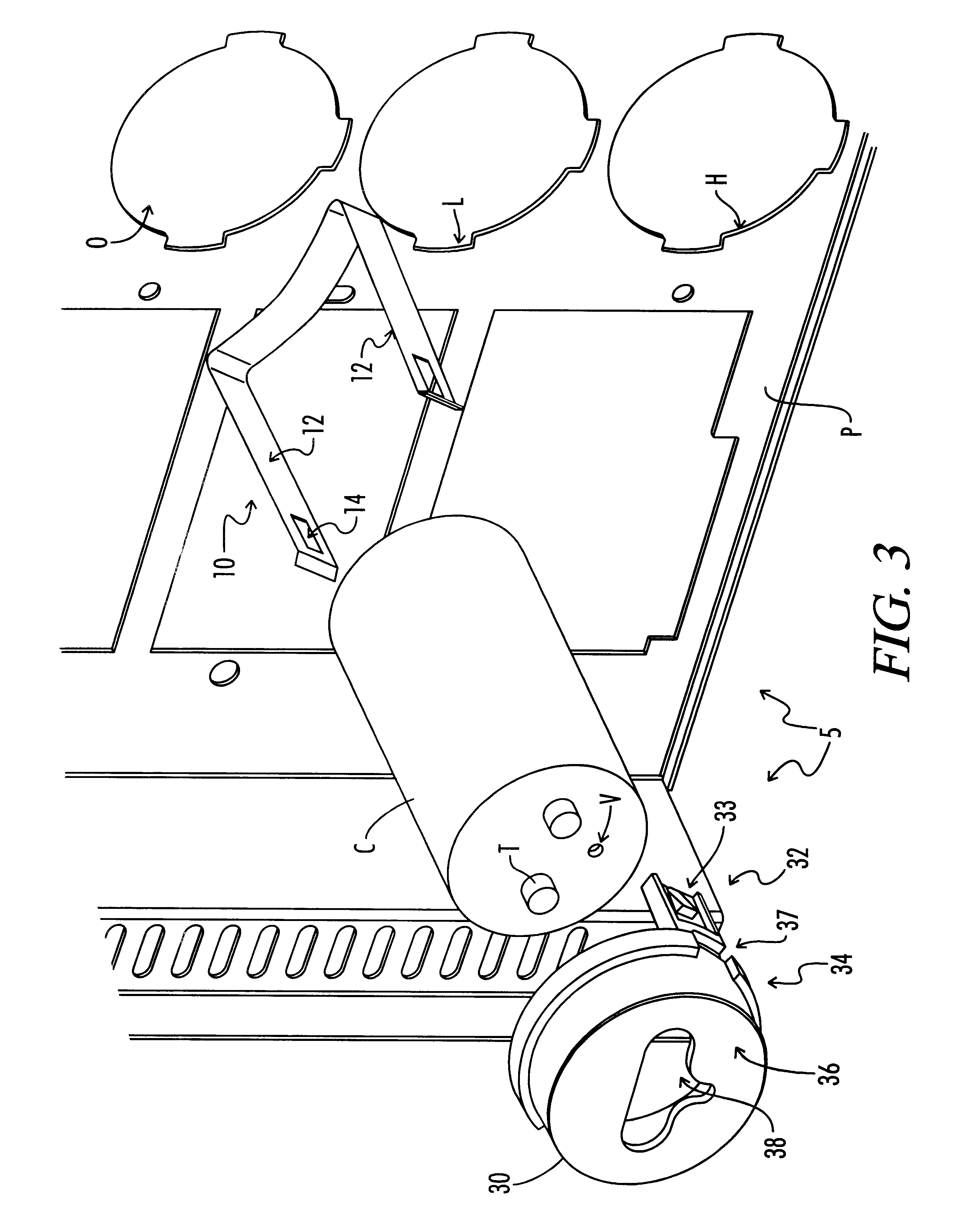
FIG. 3 shows an exploded view of the invention, a capacitor holder 5, prior to installation in a panel P having a panel opening O for receiving a capacitor C. The capacitor C includes a capacitor top and a capacitor bottom. Terminals T extend upward from the capaci...


PUM


Abstract

A capacitor holder for mounting capacitors used in electronics assemblies into a fixture, as well as mounting other types of components in other panels. The capacitor holder includes a support for receiving the capacitor and a cover for covering the capacitor. The cover and the support are attached to each other without the use of separable fasteners. Typically, snap-fit tabs depending from the cover are used to attach the cover to the support with a capacitor there between to form an assembly. The assembly is mounted into a fixture panel without the use of separable fasteners. In another typically embodiment, the mounting members are push-in and twist or push-in and snap-fit members integral with the cover. Thus, the capacitor is mounted within a fixture without separable fasteners. A method of aligning the capacitor within the panel is also disclosed.

Description

BACKGROUND OF THE INVENTIONThe present invention relates generally to mounting brackets. More particularly it relates to a mounting structure used to mount capacitors used in motor drives. Present mounting systems generally consist of sheet metal clamps that grip around the body of the capacitor and bolt to an assembly panel with the use of threaded fasteners.U.S. Pat. No. 4,712,162 (Quiogue) discusses the requirement for a variety of clamping brackets to mount capacitors of varying sizes into electronic controls or fixtures. Quiogue discloses a hold-down strap to compensate for the variety of clamping bracket sizes and designs used. The hold-down strap uses screw and nut fasteners, as do most clamping brackets.U.S. Pat. No. 4,937,718 (Murray) discloses a mounting bracket for receiving and mounting the capacitor to a support surface with screw and nut fasteners. The mounting bracket in Murray has a deformable plane intersecting a second deformable plane. The first plane section is s...

Claims


Application Information

Patent Timeline
Patent Type & Authority Patents(United States)
IPC IPC(8): H01G2/10H01G2/02G12B9/00H01G2/00H01G2/04
CPCH01G2/04
Inventor KITSCHA, JOHNPOMES, JIM
Owner MAGNETEK
Why Eureka
Try Eureka