Fuel injection control system

a control system and fuel injection technology, applied in the direction of electric control, machines/engines, liquid fuel feeders, etc., can solve the problems of long available injecting time, high-speed, high-load applications of direct cylinder injected engines or indirectly injected engines featuring certain configurations of injectors, and the transistor is susceptible to rapid temperature rise,

Inactive Publication Date: 2001-06-19
SANSHIN KOGYO CO LTD
View PDF4 Cites 13 Cited by
  • Summary
  • Abstract
  • Description
  • Claims
  • Application Information

AI Technical Summary

Problems solved by technology

The rapid opening and closely results in longer available injecting time.
The transistor, therefore, is susceptible to rapid increases in temperature over time.
Accordingly, high-speed, ...

Method used


Image

  • Fuel injection control system
  • Fuel injection control system
  • Fuel injection control system

Examples


Embodiment Construction

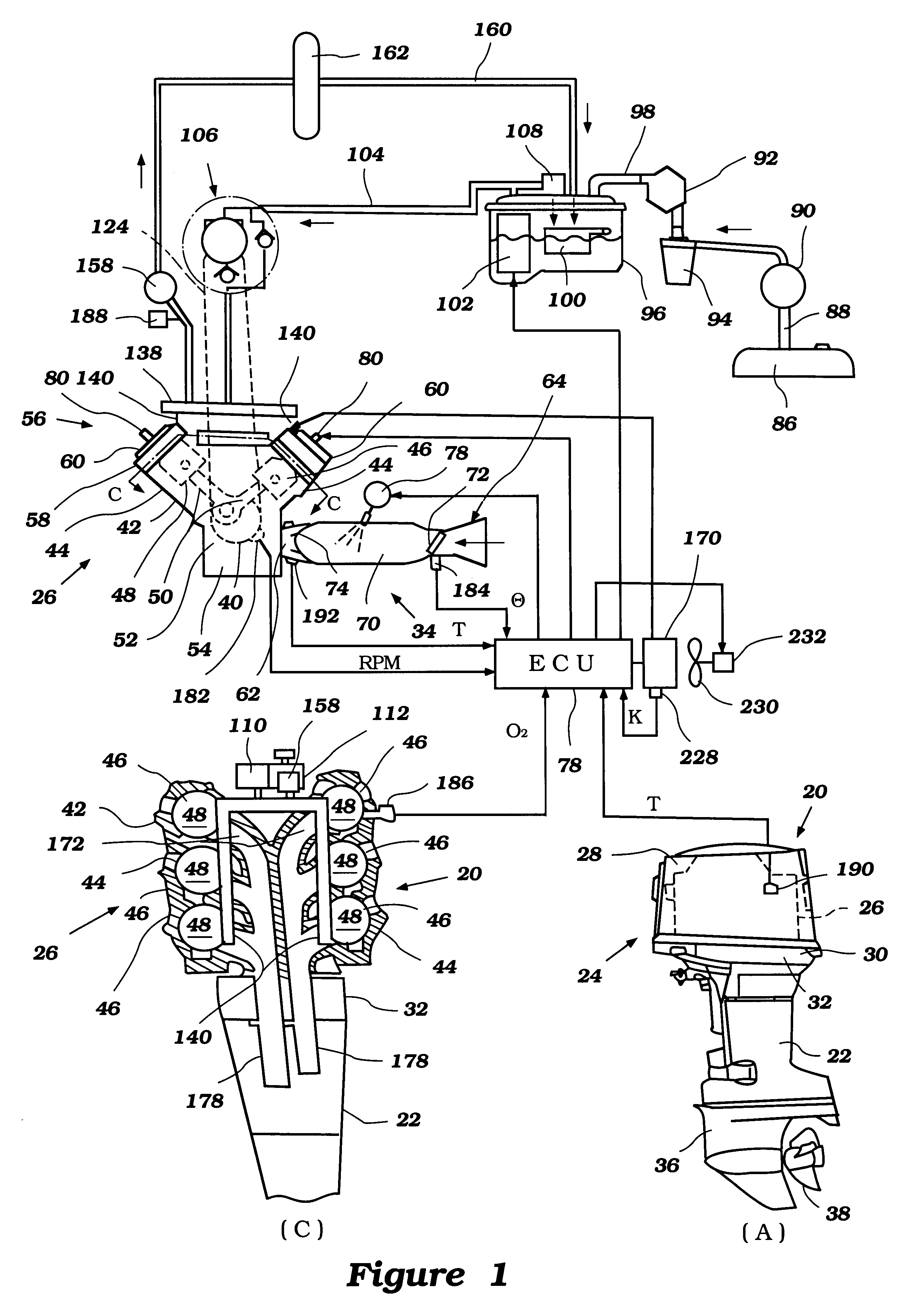
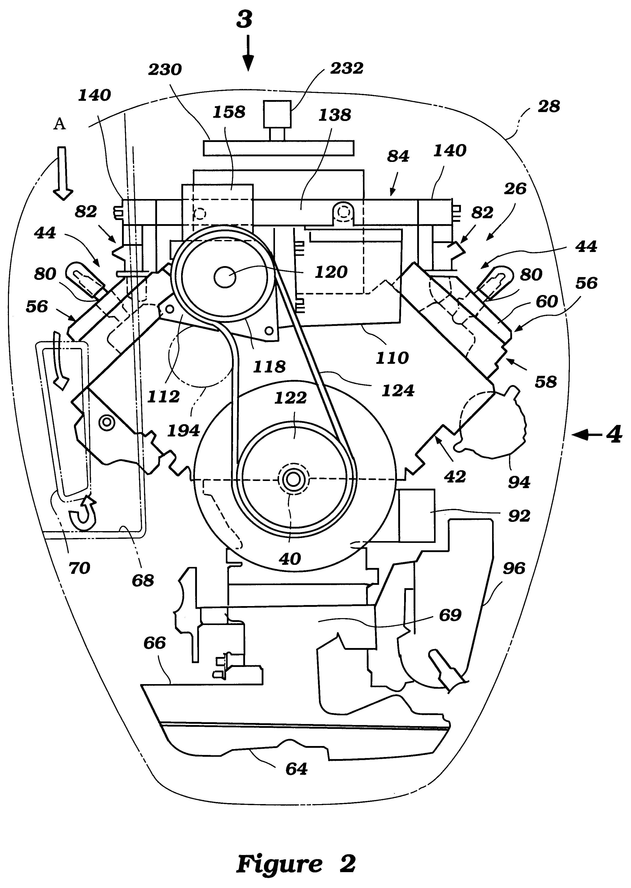
With reference initially to FIGS. 1 through 4, an outboard motor with a fuel injector control system having features, aspects and advantages in accordance with an embodiment of the present invention will be described. In the lower-right hand view of FIG. 1 (i.e., FIG. 1(A)), the outboard motor is depicted in side elevational view and is identified generally by the reference numeral 20.

The entire outboard motor 20 is not depicted in that a swivel bracket and clamping bracket that are usually associated with a drive shaft housing, indicated generally by the reference numeral 22, are not illustrated. It should be understood that these components are well known in the art. Moreover, disclosure of any specific method by which the outboard motor 20 is mounted to a transom of an associated watercraft is not necessary to permit those skilled in the art to understand or practice the present fuel injection control system without undue experimentation.

The outboard motor 20 generally comprises ...


PUM


Abstract

An outboard motor has a fuel injected internal combustion engine operating on either a two-cycle or four-cycle principle. In some embodiments, the engine is directly injected while in others it is indirectly injected. The engine features one of a number of methods for reducing the temperature of injector drivers. The methods include sensing the temperature of the injector drivers and decreasing the engine speed if the temperature exceeds a predetermined temperature. Another method involves sensing the duration of a high-speed, high-load operating condition and slowing the engine speed if the duration exceeds a predetermined time period. Yet another method involves activating a cooling fan if the temperature of the injector drivers exceeds a predetermined temperature and activating a warning device if the temperature does not decrease with the fan operating.

Description

1. Field of the InventionThe present invention generally relates to a fuel-injected engine for an outboard motor. More particularly, the present invention relates to an improved fuel injection control system for a direct injection internal combustion engine used in a marine environment.2. Related ArtTwo cycle engines are widely used, particularly in applications where high specific outputs and relatively uncomplicated, simple engine constructions are desirable. Thus, two cycle engine are frequently employed as the power plant in a marine outboard motor because of the small space available in the powerhead of such engines and the demand for relatively high performance.However, because of environmental concerns, there is a desire to significantly improve the performance of two cycle engines particularly in the area of exhaust emission control. One particularly advantageous method for reducing unburned hydrocarbons in the exhaust emissions without sacrificing engine performance is usin...

Claims


Application Information

Patent Timeline
IPC IPC(8): F02D37/00F02D41/22F02D37/02F02M69/46F02B61/00F02B61/04F02M51/00F02B75/18F02B75/00F02B75/02F02B69/00F02B69/06F01P1/06F01P1/10F02D41/02F02D41/34
CPCF02B61/045F02D37/02F02D41/221F02M51/005F02M69/462F02M69/465F02B69/06F02B2075/025F02B2075/027F02B2075/1824F02D2041/2048F02D2041/2065F02D2041/228F02D2400/04F02M2200/24
Inventor SATO, TAKAYUKIKATO, MASAHIKOMOTOSE, HITOSHI
Owner SANSHIN KOGYO CO LTD
Why Eureka
Try Eureka