Inverted radial back-curling thermoelastic ink jet printing mechanism

Inactive Publication Date: 2001-06-19
SILVERBROOK RES PTY LTD +1
View PDF4 Cites 184 Cited by
  • Summary
  • Abstract
  • Description
  • Claims
  • Application Information

AI Technical Summary

Problems solved by technology

Each technology may have its own advantages and disadvantages in the areas of cost, speed, quality, reliability, power usage, simplicity of construction and operation, durability and consumables.

Method used


Image

  • Inverted radial back-curling thermoelastic ink jet printing mechanism
  • Inverted radial back-curling thermoelastic ink jet printing mechanism
  • Inverted radial back-curling thermoelastic ink jet printing mechanism

Examples


Embodiment Construction

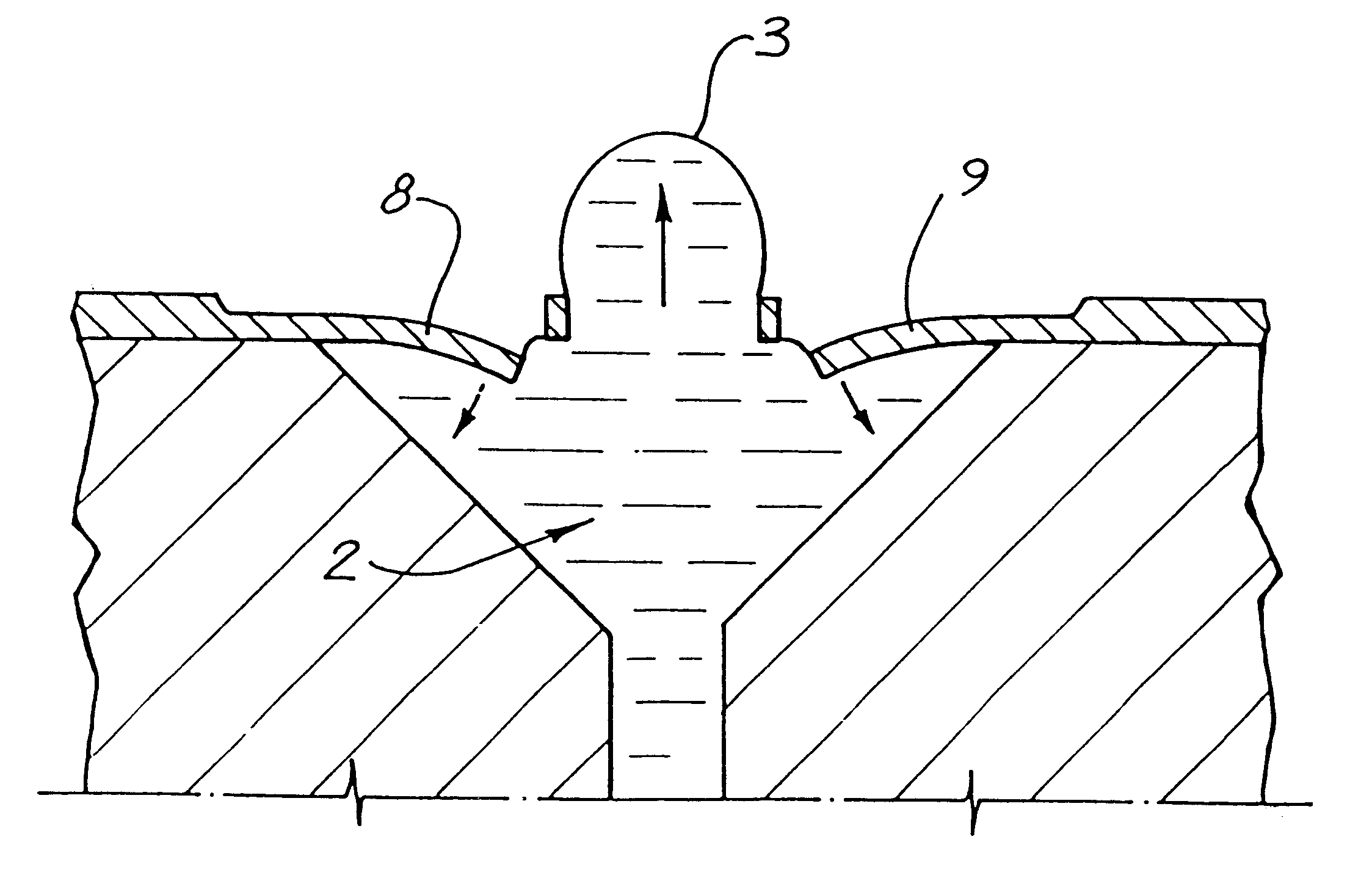
In the preferred embodiment, ink is ejected out of a nozzle chamber via an ink ejection port using a series of radially positioned thermal actuator devices that are arranged about the ink ejection port and are activated to pressurize the ink within the nozzle chamber thereby causing the ejection of ink through the ejection port.

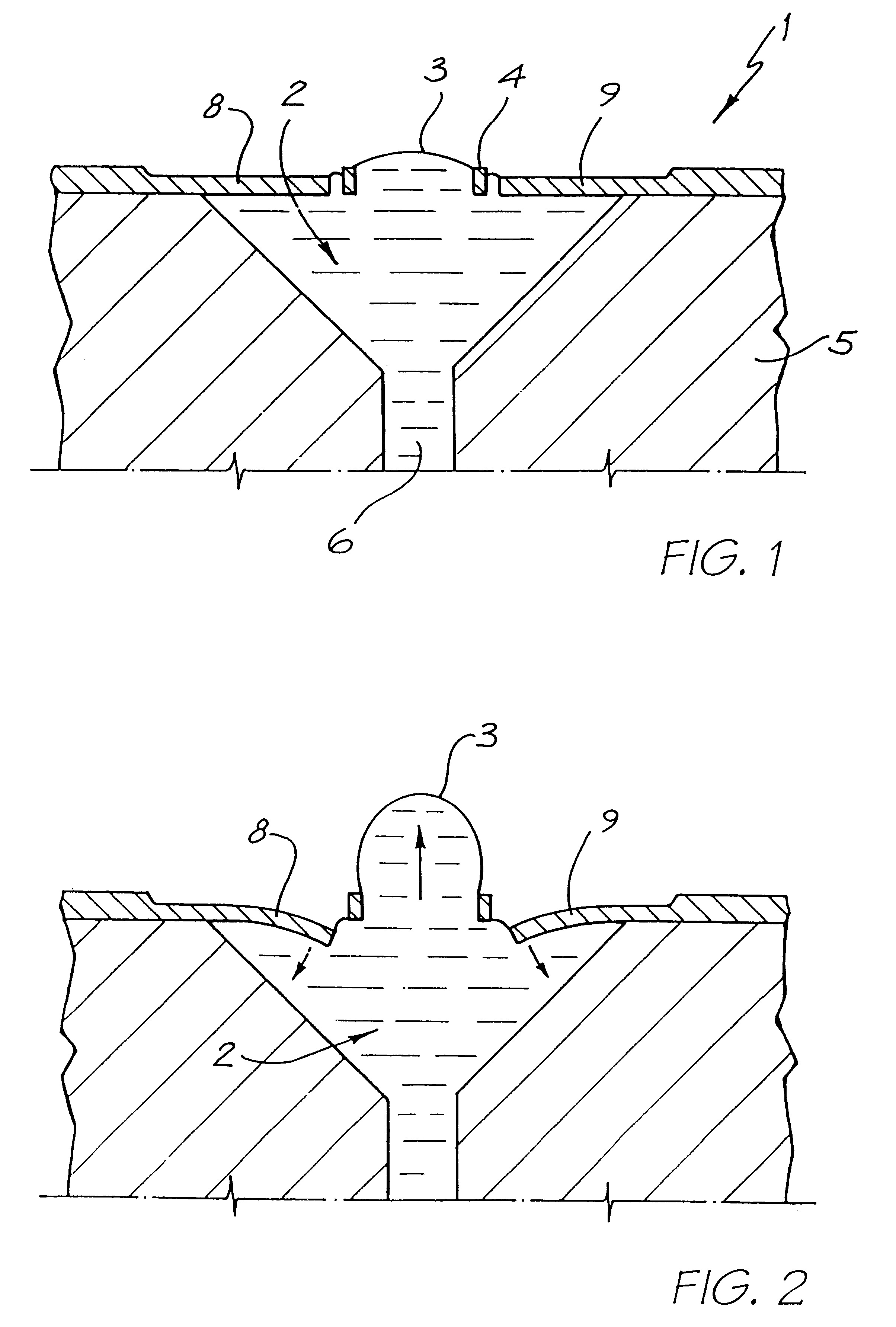
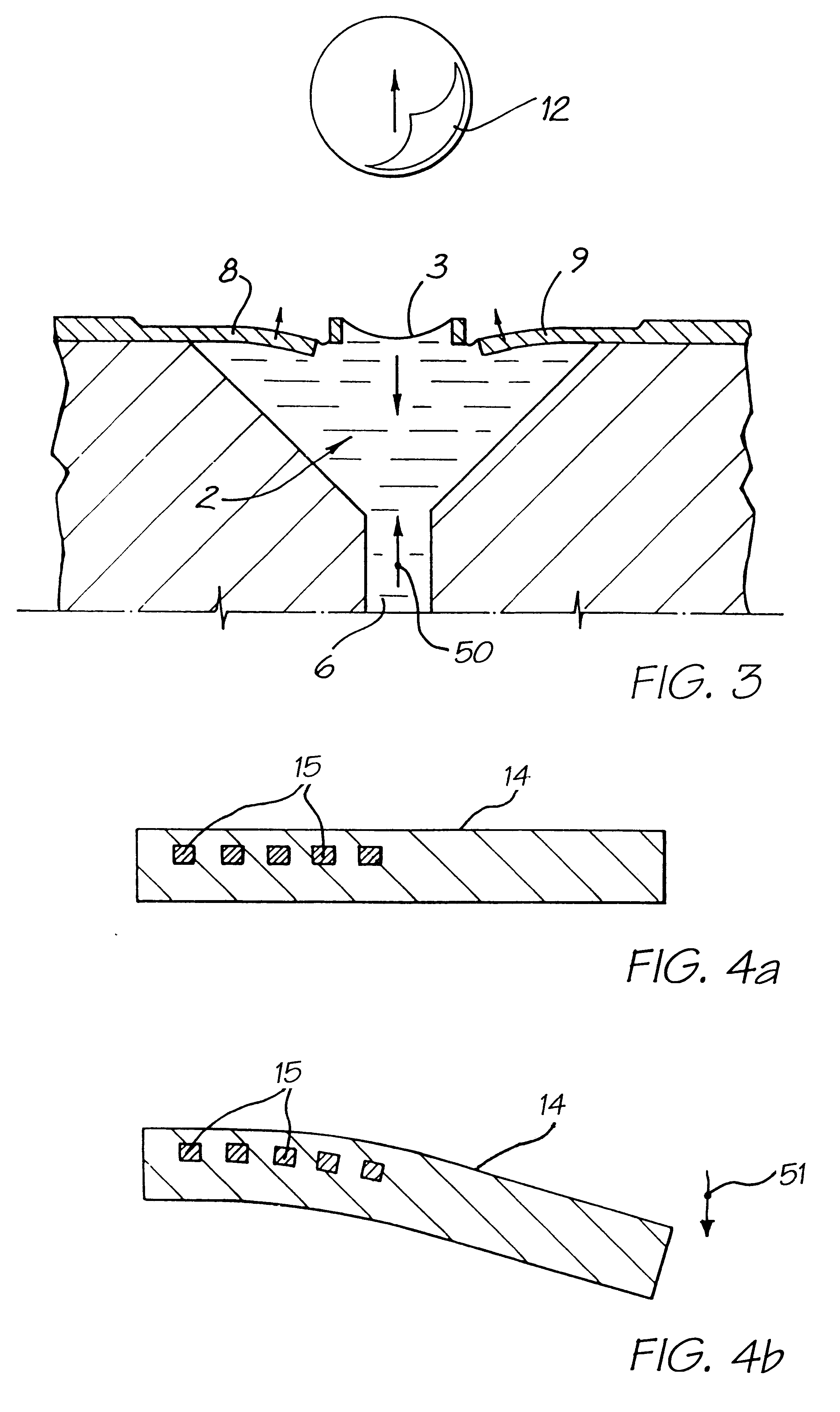
Turning now to FIGS. 1, 2 and 3, there is illustrated the basic operational principles of the preferred embodiment. FIG. 1 illustrates a single nozzle arrangement 1 in its quiescent state. The arrangement 1 includes a nozzle chamber 2 which is normally filled with ink so as to form a meniscus 3 in an ink ejection port 4. The nozzle chamber 2 is formed within a wafer 5. The nozzle chamber 2 is supplied with ink via an ink supply channel 6 which is etched through the wafer 5 with a highly isotropic plasma etching system. A suitable etcher can be the Advance Silicon Etch (ASE) system available from Surface Technology Systems of the United Kingdom.

A top of the no...


PUM

PropertyMeasurementUnit
depthaaaaaaaaaa
depthaaaaaaaaaa
poweraaaaaaaaaa

Abstract

A nozzle arrangement for an ink jet printhead includes a wafer substrate having a nozzle chamber defined therein. The nozzle arrangement has a nozzle chamber wall that defines an ink ejection port and a rim about the ink ejection port. A series of radially positioned actuators are connected to the wafer substrate and extend radially inwardly towards the rim. Each actuator is configured so that a radially inner edge of each actuator is displaceable, with respect to the nozzle rim, into the chamber, upon actuation of the actuator and so that, upon such displacement, a pressure within the nozzle chamber is increased, resulting in the ejection of ink from the ejection port.

Description

Not applicable.1. Field of the InventionThe present invention relates to the field of inkjet printing and, in particular, discloses an inverted radial back-curling thermoelastic ink jet printing mechanism.2. Background of the InventionMany different types of printing mechanisms have been invented, a large number of which are presently in use. The known forms of printers have a variety of methods for marking the print media with a relevant marking media. Commonly used forms of printing include offset printing, laser printing and copying devices, dot matrix type impact printers, thermal paper printers, film recorders, thermal wax printers, dye sublimation printers and ink jet printers both of the drop on demand and continuous flow type. Each type of printer has its own advantages and problems when considering cost, speed, quality, reliability, simplicity of construction and operation etc.In recent years the field of ink jet printing, wherein each individual pixel of ink is derived fro...

Claims


Application Information

Patent Timeline
Patent Type & Authority Patents(United States)
IPC IPC(8): B41J2/14B41J2/16B41J2/175B41J2/04B41J2/05
CPCB41J2/14B41J2/14427B41J2/16B41J2/1623B41J2/1628B41J2/1629B41J2/1631B41J2/1632B41J2/1635B41J2/1637B41J2/1639B41J2/1642B41J2/1648B41J2/17596B41J2/1433Y10T29/4913B41J2002/041B41J2002/14346B41J2002/14435B41J2002/14475B41J2202/15Y10T29/49401Y10T29/49155Y10T29/49128Y10T29/49156
Inventor SILVERBROOK, KIAMCAVOY, GREG
Owner SILVERBROOK RES PTY LTD
Why Eureka
Try Eureka