Flat and planar match system between rails and fillers to railroad turnouts and crossings

a rail and filler technology, applied in railway tracks, railway tracks, constructions, etc., can solve the problems of difficult to achieve a proper match between rails, filler blocks and filler members, reduced relative strength of assembled structures, and difficulty in alignment and installation. , to achieve the effect of improving load transfer, improving strength and improving alignment and installation

Inactive Publication Date: 2001-07-03
ORTIZ RIVAS ARTURO A
View PDF6 Cites 4 Cited by
  • Summary
  • Abstract
  • Description
  • Claims
  • Application Information

AI Technical Summary

Benefits of technology

The filler members according to the present invention are attached to a rail in the railroad track structure for support purposes. The filler members include a filler member body which has a laterally outwardly extending vertical contact surface which engages a corresponding flat vertical surface on a web portion of the rail. The filler members include a leg member extending downwardly from the filler member body. The leg member has a horizontal contact surface for mounting on a corresponding horizontal flat surface formed on a sloped surface of a base portion of the rail. The filler members also have an upwardly extending upright which has a horizontal planar upper contact surface to engage a corresponding horizontal flat surface formed below a head portion of the rail. The engagement of the horizontal and vertical surfaces on the filler member with corresponding surfaces on the rail provides ease of alignment and installation, as well as increased strength and better load transfer.
The filler blocks of the present invention are attached between adjacent rails in the railroad track structure. The filler blocks include a filler block body which has a laterally outwardly extending vertical contact surface formed on it to engage corresponding planar flat vertical surfaces formed on web portions of the adjacent rails. The filler block body has a horizontal lower contact surface on a lower surface for mounting on corresponding horizontal flat surfaces formed on base portions of the adjacent rails. The filler block bodies also have one or more uprights formed extending upwardly, having horizontal upper contact surfaces formed on them. The upper contact surfaces on the uprights engage corresponding horizontal flat surfaces below head portions of the adjacent rails. The engagement of the horizontal and vertical contact surfaces of the filler blocks with corresponding surfaces on the adjacent rails provides ease of alignment and installation, also increasing strength and improving lead transfer.
Railroad structures with filler members and filler blocks according to the present invention thus have increased strength and extended service life. These structures are also more easily aligned and installed, and are more easily maintained.

Problems solved by technology

However, problems have been found to exist.
It was thus difficult to achieve a proper match between the rails, filler blocks and filler members when track structures such as frogs and crossings were assembled.
To the extent that a properly fitted match between these three contact surfaces was not achieved, the relative strength of the assembled structure was reduced, and the service life of the structure decreased.
This could in some cases after time pose a possible safety concern.

Method used


Image

  • Flat and planar match system between rails and fillers to railroad turnouts and crossings
  • Flat and planar match system between rails and fillers to railroad turnouts and crossings

Examples


Embodiment Construction

:

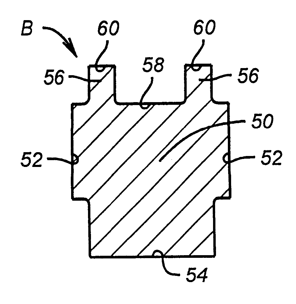
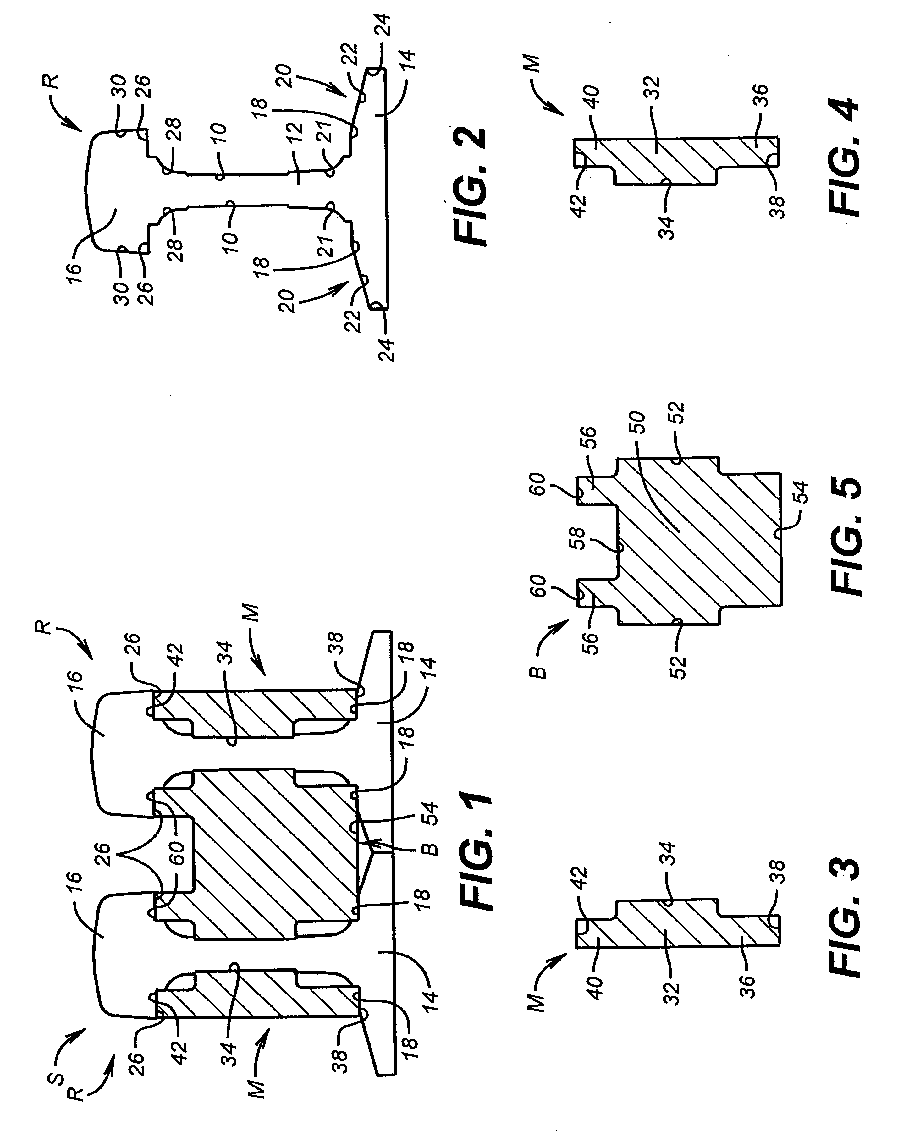
In the drawings, the letter S designates generally a railroad track structure formed between a pair of adjacent track components, such as rails R. The structure S also includes a pair of filler members M and a filler block body B. The railroad structure S may be a frog, turnout or crossing, as disclosed in U.S. Pat. Nos. 5,765,785; 5,393,019 and 5,303,884, each of which is incorporated herein by reference.

Turning first to the rails R, each of such rails has a flat vertical surface 10 formed on each side of a web portion 12 between a base portion 14 and a head portion 16. The flat vertical surfaces on the rail web 12 are formed in the manner disclosed in Applicant's U.S. Pat. No. 5,765,785, which is incorporated herein by reference. The vertical flat surfaces 10 serve as precise measurement and alignment references for other surfaces formed on the rails R and other components of the structure S, as will be set forth below.

Each of the rails R also includes a horizontal flat surface 1...


PUM


Abstract

The strength and reliability of railroad track structures, such as frogs, crossings, and guardrails, is enhanced. Filler members and filler blocks are fitted in to support and strengthen the structures. The filler members and filler blocks provide better matching and alignment of load transfer surfaces. The track structures with the improved components are more easy to align and assemble. The strength of the assembled track and structures is also increased, and the structures are more easily maintained.

Description

BACKGROUND OF THE INVENTION:1. Field of the InventionThe present invention relates to railroad track components for turnouts, crossings and the like.2. Description of Prior ArtU.S. Pat. No. 5,765,785 of which Applicant is inventor, provided certain improvements in railroad track crossings. Among these were a new and improved railroad track crossing which included an interchangeable insert. Among the components of the structure were support fillers and filler blocks. These two structural components had vertical contact surfaces on side portions which were adapted to mate with and fit against corresponding flat vertical surfaces formed on the upright web portion of the rail. The support fillers and filler blocks also had downwardly sloping upper and lower surfaces. These sloping surfaces were intended to conform or correspond to the conventional sloped planar surfaces present in rails or other track pieces. These sloped planar surfaces were present in rails below the wheel contact por...

Claims


Application Information

Patent Timeline
Patent Type & Authority Patents(United States)
IPC IPC(8): E01B7/00
CPCE01B7/00
Inventor ORTIZ RIVAS, ARTURO A.
Owner ORTIZ RIVAS ARTURO A
Why Eureka
Try Eureka