
Tampon with a tampon applicator

Inactive Publication Date: 2001-07-03
THE PROCTER & GAMBLE COMPANY
View PDF6 Cites 33 Cited by
  • Summary
  • Abstract
  • Description
  • Claims
  • Application Information

AI Technical Summary

Benefits of technology

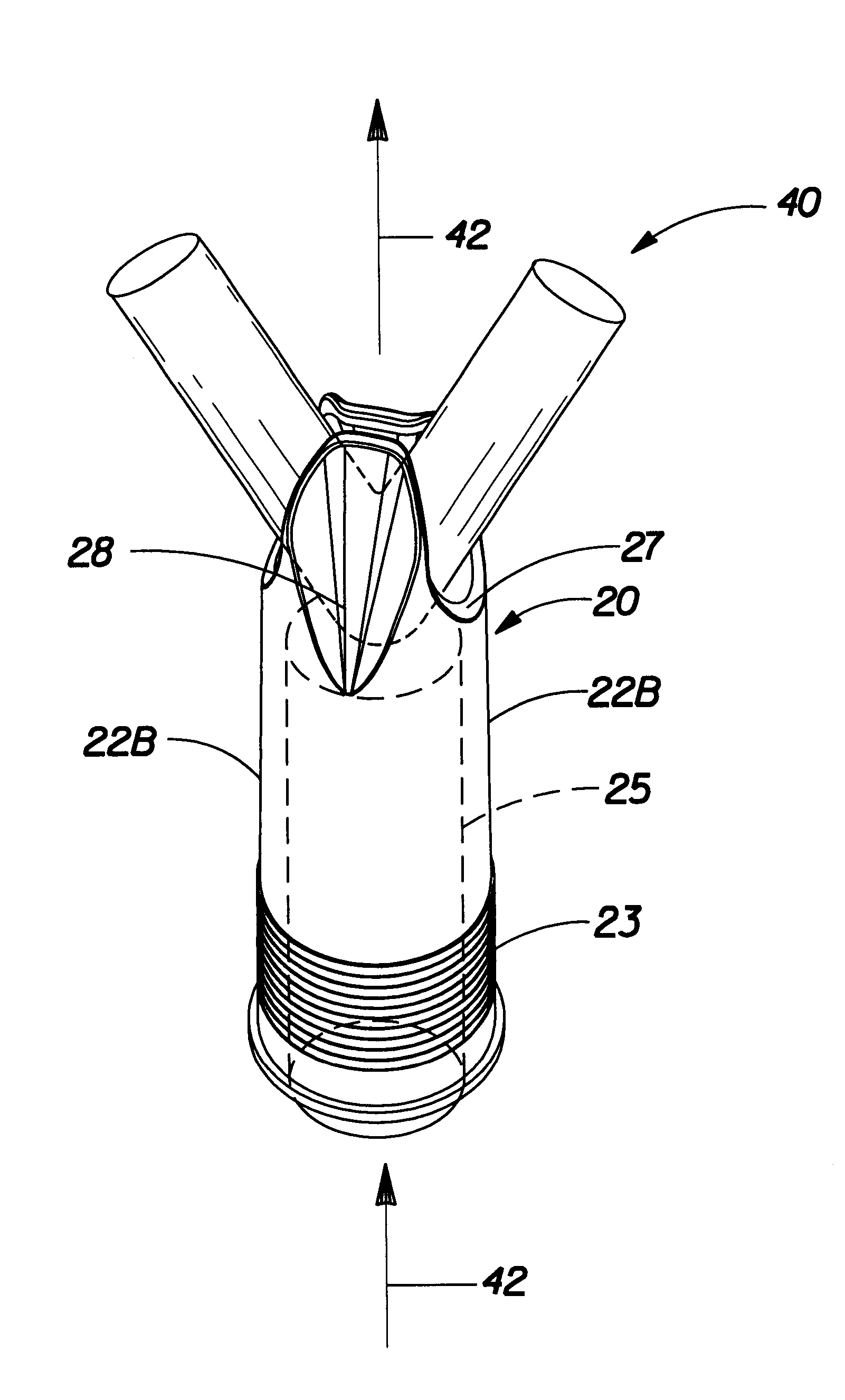
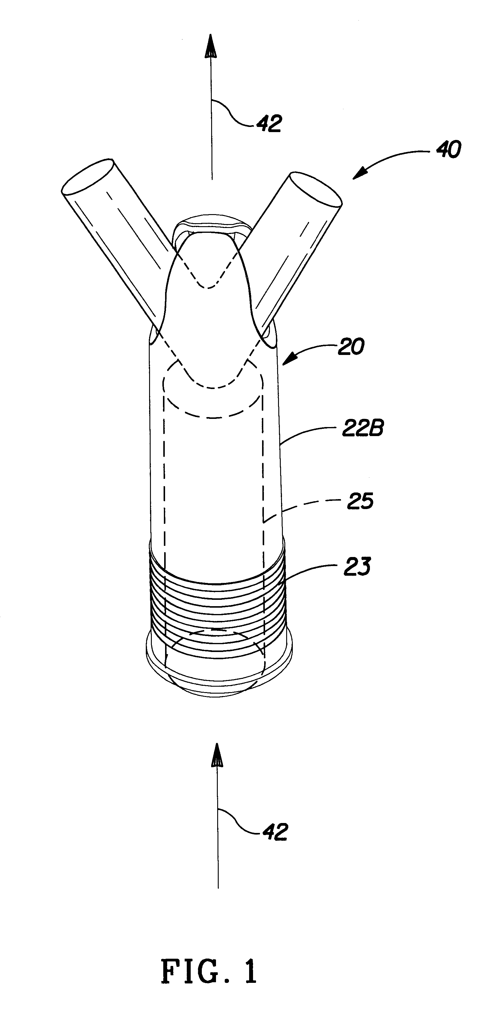
Another series of attempts to overcome the problems associated with conventional, highly compressed, fluid expanding tampons is described in U.S. Patent No. 3,749,094 issued to Duncan and U.S. Patent Nos. 3,794,029 and 3,766,921 both issued to Dulle. The Duncan and Dulle devices are all generally conical and are designed to be dry-expanding. While these devices would be expected to overcome some of the problems associated with highly compressed, fluid expanding tampons, the Duncan and Dulle devices still require significant rigidity and compression in order to permit their use in a conventional "tube and plunger" type applicator for which they are designed. It has been found during development of the present invention that a tampon constructed according to the invention described herein can provide even further improvements in comfort, low wearing awareness, and performance as compared to currently marketed tampons and previous attempts to improve upon such tampons such as those described above. The present invention aims to provide a structure with the advantages of petal-type applicators, and especially providing for side-to-side coverage, but minimizing the disadvantages noted above.

Problems solved by technology

Obviously, from such a construction, the tampon applicator of FIG. 15 can provide little if any directional expulsion of a tampon within the vagina of a female user and thus can provide no side-to-side coverage of a tampon within the vagina of a female user.

Method used


Image

  • Tampon with a tampon applicator
  • Tampon with a tampon applicator
  • Tampon with a tampon applicator

Examples


example no.1

Example No. 1

"V" 14 mm Tubular--(2Tubes side by side w / punch & loop cord attachment and PP Overwrap width)

PRODUCTION AIDS NEEDED:

TAMPON MAKING INSTRUCTIONS ("V"14 mm PP Overwrap)

Using the 25.4.times.160 mm Die "Core" Cutter, cut the strips of Tampax Regular absorbency core material and set aside. Cut a (minimum of 150 mm) long section of Sandler polypropylene overwrap and place onto the work surface. Fold the PP overwrap in half lengthwise. Align the PP folded edge with the 14 mm marking on the sewing machine and sew a seam along the length of the PP forming a tube. Trim any excess materials from the sewn edge to ensure smooth edges. Using the Ezy-Pull tool, invert the PP tubing. (Ensuring that sewn seam is inside of the tube). Place the core material on the plastic, fold it in half and roll to form a funnel out of the plastic and a tube out of the core material. Insert the materials into the pre-made PP tubing (pulling core through and removing plastic tube). Try to ensure that the...

example no.2

Example No. 2

"V"14 mm Tubular--(PP Overwrap width)

PRODUCTION AIDS NEEDED:

TAMPON MAKING INSTRUCTIONS ("V"14 mm PP Overwrap)

Using the 25.4.times.160 mm Die "Core" Cutter, cut the strips of Tampax Regular absorbency core material and set aside. Cut a (minimum of 150 mm) long section of Sandler polypropylene overwrap and place onto the work surface. Fold the PP overwrap in half lengthwise. Align the PP folded edge with the 14 mm marking on the sewing machine and sew a seam along the length of the PP forming a tube. Trim any excess materials from the sewn edge to ensure smooth edges. Using the Ezy-Pull tool, invert the PP tubing. (Ensuring that sewn seam is inside of the tube). Place the core material on the plastic, fold it in half and roll to form a funnel out of the plastic and a tube out of the core material. Insert the materials into the pre-made PP tubing (pulling core through and removing plastic tube). Try to ensure that the folded edge of the core with the seam line of the tubin...

example no.3

Example No. 3

SEWN "V" & KITE


PUM


Abstract

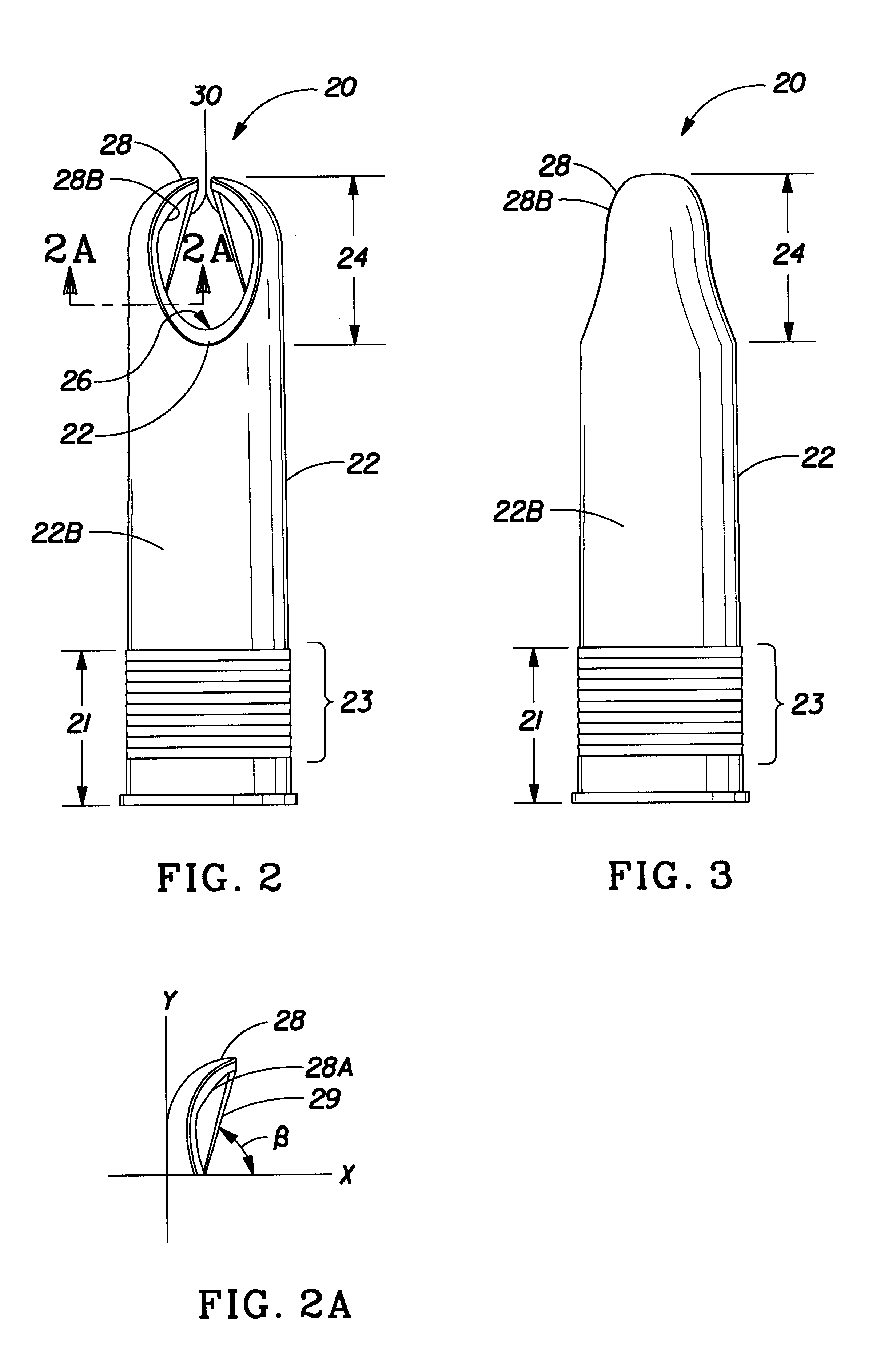
A suitable tampon with a tampon applicator for expelling the tampon to provide side-to-side coverage and inserting the tampon into a body cavity is provided. The tampon applicator has a tampon holder tube having interior and exterior surfaces, a longitudinal axis, a hollow portion and an expulsion end dimensioned for insertion into the body cavity. The tampon holder tube has a feature for separating and spreading a tampon apart during expulsion of the tampon. A plunger may also be telescopically and slidably mounted in the tampon holder tube distal to the expulsion end and adapted to directionally expel the tampon from the tampon holder tube when a user expels the tampon from the tampon holder tube.

Description

The invention provides a novel tampon applicator having a tampon expulsion feature providing directed expulsion of a tampon.Tampon applicators comprising a plurality of telescopically-arranged tubes are known. Such applicators are, however, either blunt ended at the end which is intended for vaginal insertion (the "expulsion end ") or, in recent years applicators have been developed which are rounded at that end, having a plurality of separated "petals" which are further spaced upon the expulsion through the end of a tampon. The telescopic tube arrangement permits one tube to be used as a plunger to force the expulsion of the tampon from another tube in which the plunger tube is slidably positioned. Although the petal format is more convenient for vaginal insertion, the prior art structures suffer from a number of disadvantages, the most significant of which is probably the tendency of the expanded petal arrangement (after expulsion of a tampon) to catch or nip tissue and hair. By w...

Claims


Application Information

Patent Timeline
IPC IPC(8): A61F13/20A61F13/26
CPCA61F13/2051A61F13/26Y10S604/904
Inventor BUCK, KIMBERLY ANNMACKAY, LISA ANNPEACE, WILLIAM PATTONSMITS, CHRISSIE MELINDATWEDDELL, III, RICHARDWEINBERGER, ERIC PATTON
Owner THE PROCTER & GAMBLE COMPANY
Learn More