Apparatus and method for determining respiratory mechanics of a patient and for controlling a ventilator based thereon

a technology of respiratory mechanics and apparatus, which is applied in the field of system and method for determining the respiratory condition of a patient and to a system and method for controlling a ventilation system, can solve the problems of increasing the patient's ventilation rate, and reducing the efficiency of the ventilation system

Inactive Publication Date: 2001-07-10
RIC INVESTMENTS LLC
View PDF16 Cites 232 Cited by
  • Summary
  • Abstract
  • Description
  • Claims
  • Application Information

AI Technical Summary

Problems solved by technology

Measuring the respiratory resistance and elastance of a spontaneously breathing patient is not a simple task.
Conventional techniques for measuring resistance and elastance are somewhat invasive in that they are performed in a clinical or hospital setting and require placing a device for measuring esophageal pressures, such as an esophageal balloon, within the patient.
However, the effect of the inertial force increases with increases in the patient's ventilation rate.
The variables known to change resistance and elastance are very complex, including flow rate, lung volume, points in the ventilatory cycle and ventilatory rate.
However, the use of nonlinear models precludes application of many powerful concepts typically employed in a clinical investigation of respiratory mechanics, such as the use of frequency-domain analysis, Bode diagrams and multilinear regression.
However, there is believed to be presently no known direct method of non-invasively measuring P.sub.mus (t) under dynamic conditions.
However, these conventional clinical techniques for determining resistance and elastance are cumbersome and cannot be performed easily on a ventilator supported patient.
Furthermore, several of these techniques require manually implemented procedures and cannot be performed using most ventilators, especially ones that exhibit system leak.
In an open circuit system, however, the system leak, e.g., exhalation or exha...

Method used


Image

  • Apparatus and method for determining respiratory mechanics of a patient and for controlling a ventilator based thereon
  • Apparatus and method for determining respiratory mechanics of a patient and for controlling a ventilator based thereon
  • Apparatus and method for determining respiratory mechanics of a patient and for controlling a ventilator based thereon

Examples


Embodiment Construction

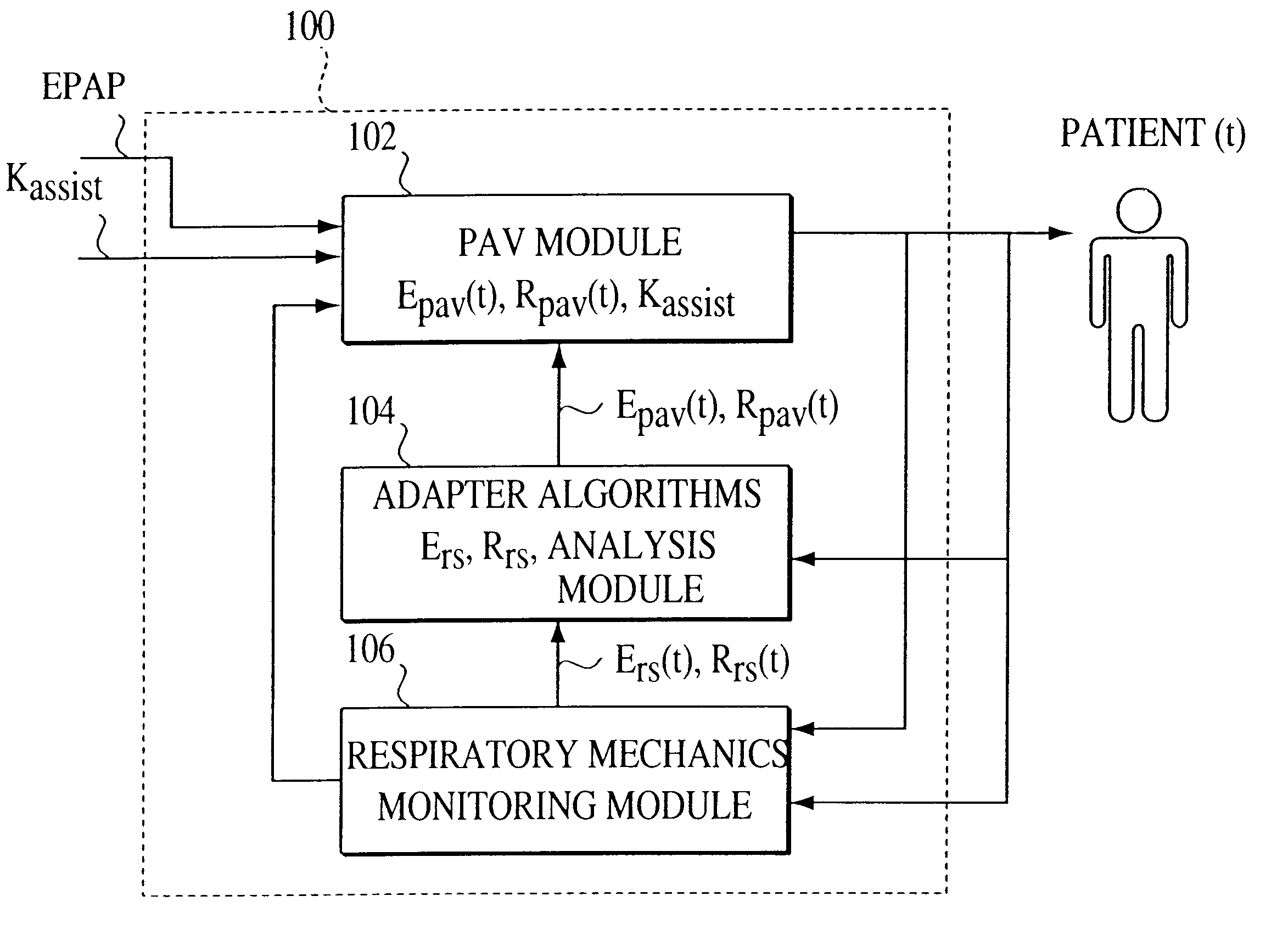
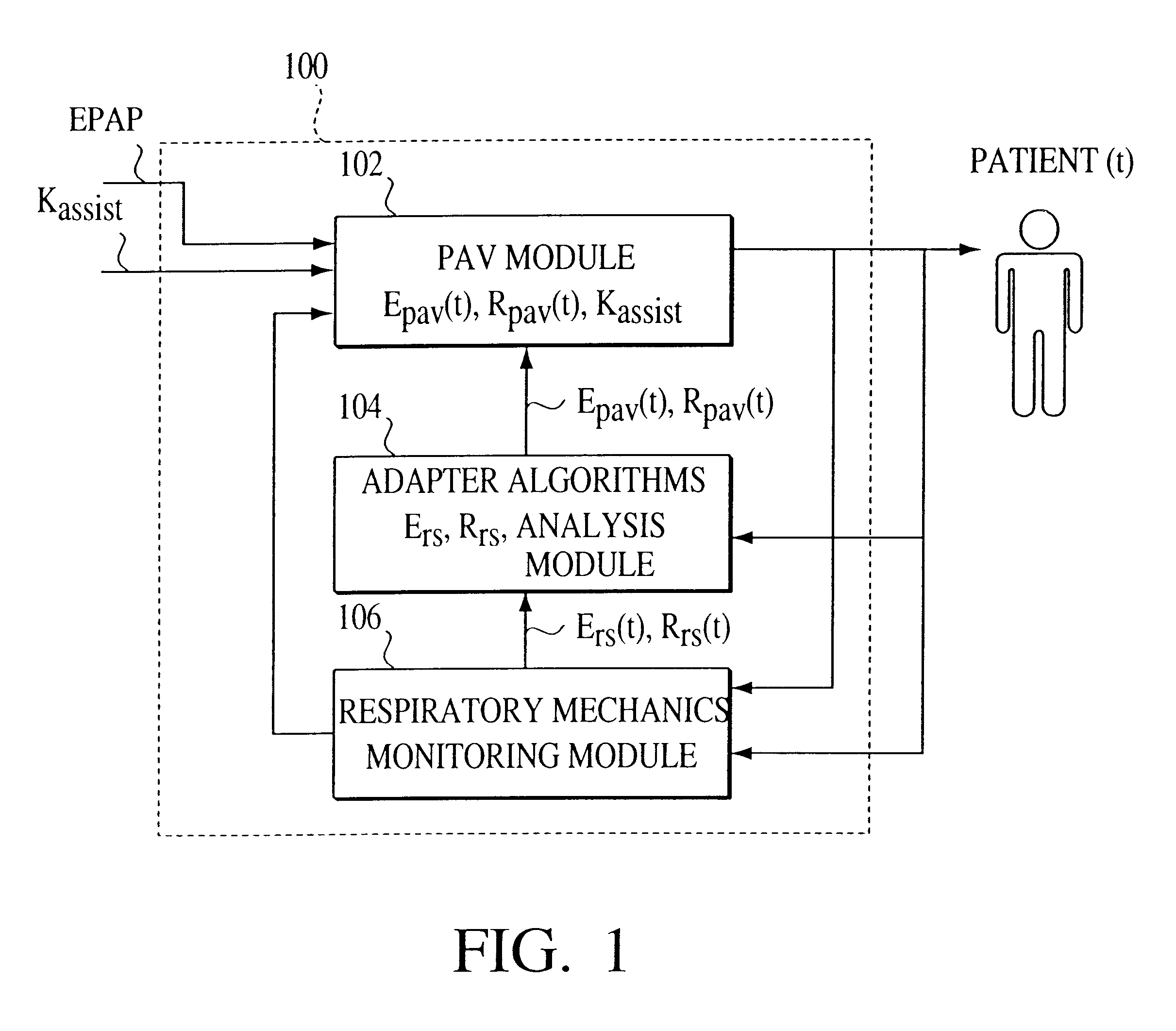
One embodiment of the present invention is referred to as an adaptive proportional assist ventilation (APAV) device and method because it enables the gains that are used in a PAV device to be automatically altered based on the current conditions of the patient. Thus, the present invention permits PAV to be performed based on the present state of the patient, as opposed to being based on a condition of the patient measured some time ago in a hospital or clinic.

As shown in FIG. 1, APAV system 100 of the present invention includes the following three modules: a PAV module 102, an adapter module 104, and a patient's respiratory mechanics monitoring module 106. Adapter module 104 can be implemented in hardware and / or software. APAV is initiated by setting a prescribed assistance rate K.sub.assist, which represents the degree of the ventilator's accommodation for the patient's breathing effort, and the EPAP, which is the patient's expiratory positive airway pressure.

Adapter module 104 obt...


PUM


Abstract

A ventilation system is controlled by detecting the resistance and elastance of the patient's respiratory system and adjusting the flow supplied by the ventilator accordingly. In one embodiment, the resistance is detected by controlling the ventilator to superimpose at least one forced single oscillation on the flow and observing the reaction of the respiratory system. In another embodiment, the elastance is detected by controlling the ventilator to supply a pressure which has the effect of temporarily occluding the respiratory system, waiting until the respiratory system has reached equilibrium, and observing the resulting state of the respiratory system. The detection techniques of these two embodiments can be used together.

Description

1. Field of the InventionThe present invention pertains to a system and method for determining a respiratory condition of a patient and to a system and method for controlling a ventilation system based on the determined condition, and, in particular, to a system and method that non-invasively measures a patient's elastance and resistance and to a ventilator that employs such a method to measure elastance and resistance during ventilation so that the ventilatory assistance provided to the patient by the ventilator is automatically adjusted to suit the needs of the patient.2. Description of Related ArtThe related art will be described with reference to the following patents and other publications, the disclosures of which are hereby incorporated by reference in their entireties into the present disclosure. Throughout the description of the related art, these references will be cited by the first-named author and the year of publication, e.g., Jackson, 1974.M. Franetzki et al, U.S. Pat...

Claims


Application Information

Patent Timeline
IPC IPC(8): A61M16/00A61B5/08A61B5/085
CPCA61M16/0051A61M16/0006A61M16/0066A61M2205/15A61M2230/46A61M2016/0036A61M16/0069A61M16/026
Inventor SUN, JIANGUO
Owner RIC INVESTMENTS LLC
Why Eureka
Try Eureka