
Zoom optical system

Inactive Publication Date: 2001-07-10
MINOLTA CO LTD
View PDF8 Cites 8 Cited by
  • Summary
  • Abstract
  • Description
  • Claims
  • Application Information

AI Technical Summary

Benefits of technology

An object of the present invention is to provide a variable magnification optical system which satisfies at a high level the demands of reciprocity of high variable magnification and compactness, even at a variable magnification ratio of 5 or greater.
Another object of the present invention is to provide a variable magnification viewfinder which assures suitable aberration characteristics over the entire zoom range, even at a high magnification ratio of 5 or greater.

Problems solved by technology

However, in the case of zoom viewfinder systems, it becomes difficult to assure that the viewfinder will have suitable aberration characteristics over the entire zoom range in conjunction with the high variable magnification.
However, at a high variable magnification ratio in the range of about 5 to about 6, it is rather difficult to assure adequate aberration characteristics over the entire zoom range.
In the aforesaid conventional constructions having a variable magnification in the range of about 3 to about 4 and being provided with a positive / negative / positive objective optical system, there is a loss of compactness due to an increase in the overall length of the objective system when obtaining high variable magnification.

Method used


Image

  • Zoom optical system
  • Zoom optical system
  • Zoom optical system

Examples


Embodiment Construction

OF VIEWFINDER CONSTRUCTION

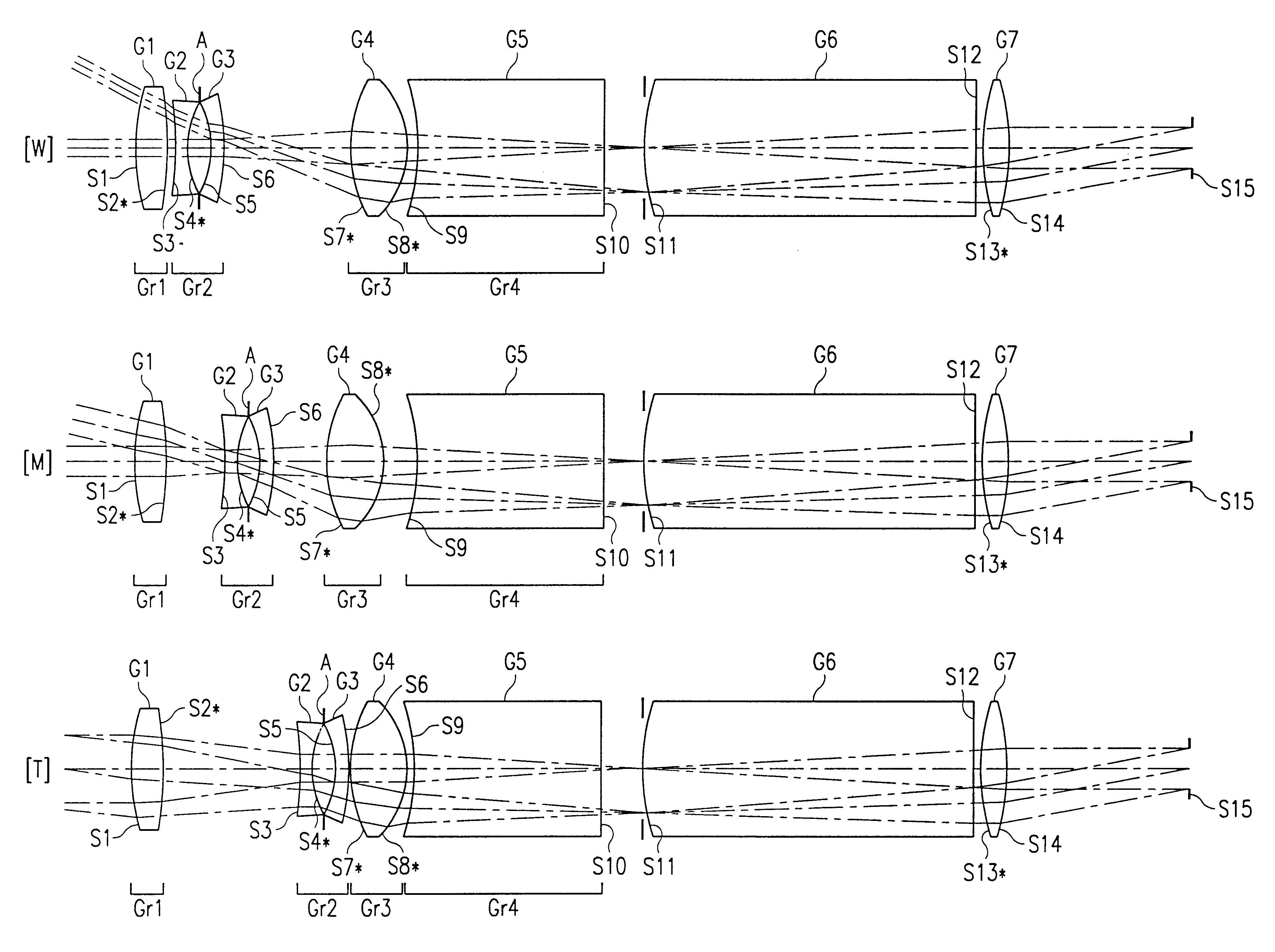
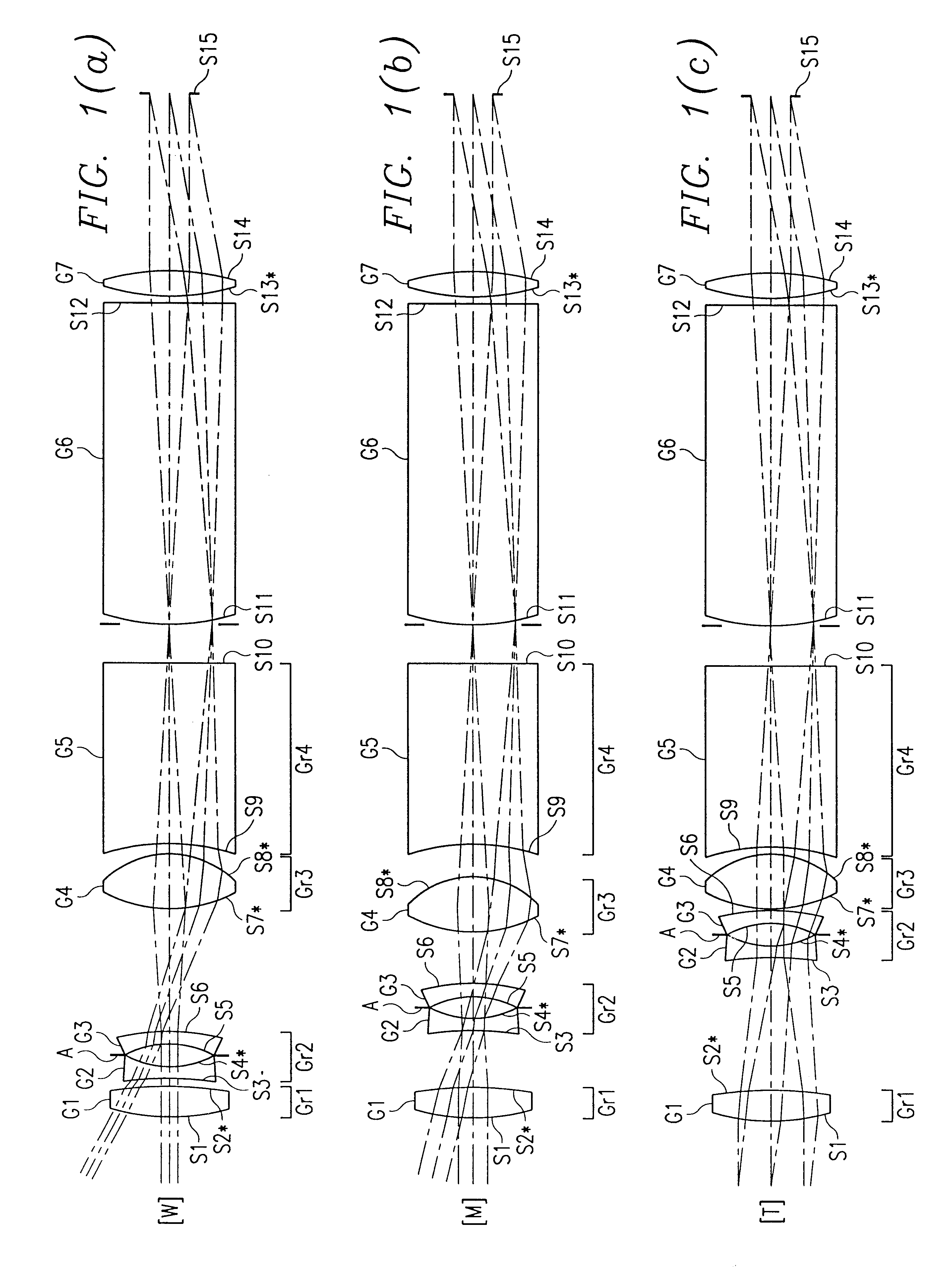
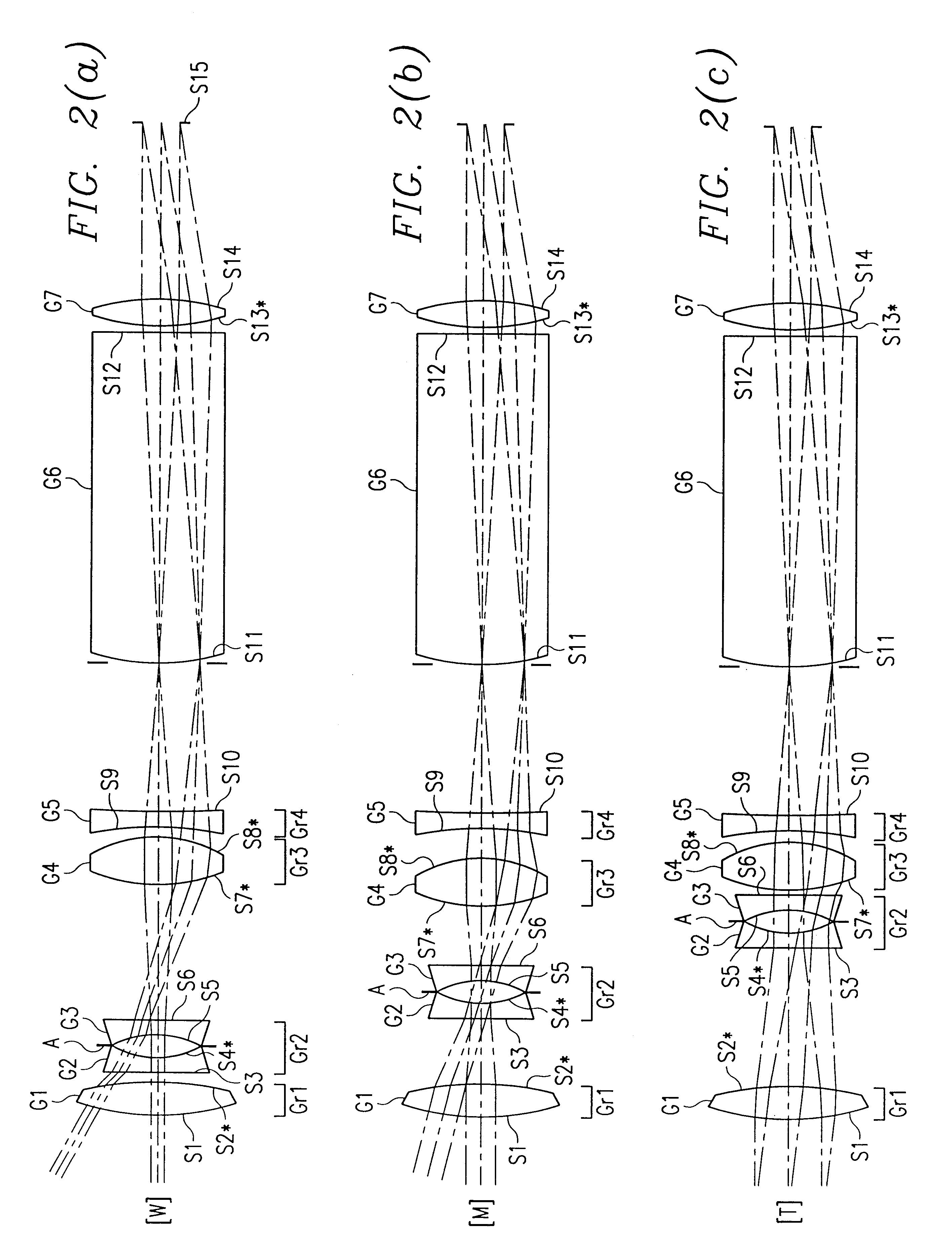
Examples of the construction of the zoom viewfinder of the present invention are described hereinafter. With reference to FIG. 12, the objective optical system of this zoom viewfinder is a four lens unit zoom system comprising four zoom lens units of the positive / negative / positive / negative type. A first lens unit Gr1 comprises a single biconvex positive lens element G1. A second lens unit Gr2 comprises two biconcave negative lens elements G2 and G3 with a light shutter panel A interposed therebetween. A third lens unit Gr3 comprises a single biconvex positive lens element G4. A fourth lens unit Gr4 comprises a single biconcave negative lens element G5. The eyepiece optical system comprises a first eyepiece prism PE1 having a roof reflective surface SD, a second eyepiece prism PE2 positioned at the entrance surface a slight distance S from the exit surface of said first eyepiece prism PE1, and a biconvex positive eyepiece lens element LE. A plane mirror M1 i...


PUM


Abstract

An objective optical system has at least three lens units having positive, negative, and positive optical powers. A fourth lens unit can have either negative or positive optical power. The system satisfies at least one of:(A) 0.15<=beta4W / FLWobj<=0.28, where beta4W represents image forming magnification of fourth lens unit at wide angle end, and FLWobj represents focal length of the system at wide angle end, and(B) the third lens unit being a biconvex lens element which satisfies the relationship Nd3>=1.6, where Nd3 represents d-line refractive index of lens material of the biconvex lens element. The system can also satisfy the relationship 0.038<=1 / FL1<=0.068 where FL1 represents focal length of first lens unit. The third lens unit can have at least one aspherical surface which, relative to a height Y in an optional direction perpendicular to the optical axis such that 0.7Ymax<Y<Ymax, satisfies the relationship -0.07<phi3.(N'-N).(d / dy){x(y)-x0(y)}<0 where phi3 represents refracting power of third lens unit, N represents d-line refractive index of medium of third lens unit for an aspherical surface on the object side, N' represents d-line refractive index of the medium for an aspherical surface on the image side, x(y) represents a shape of the aspherical surface, and x0(y) represents a reference spherical surface shape of the aspherical surface.

Description

This application is based on Japanese Patent Application No. 9-138739 and Japanese Patent Application 9-138559, the entire contents of each of which is incorporated herein by reference.1. Field of the InventionThe present invention relates to a variable magnification optical system, and more specifically relates to a compact, high-magnification zoom viewfinder optical system of the real image type which is provided separately from the photographic lens of a lens-shutter type camera or the like.2. Description of the Related ArtIn recent years, the demand has grown for cameras having greater functionality. Demand has also increased for viewfinder units, having correspondingly high variable magnification, for use in cameras which are provided with a viewfinder as a completely separate unit from the photographic system. However, in the case of zoom viewfinder systems, it becomes difficult to assure that the viewfinder will have suitable aberration characteristics over the entire zoom ra...

Claims


Application Information

Patent Timeline
IPC IPC(8): G02B15/163G02B15/173
CPCG02B15/173G02B15/144105G02B15/144113
Inventor KASAI, ICHIRO
Owner MINOLTA CO LTD
Learn More