
Variable focal length lens system and image capturing apparatus

Inactive Publication Date: 2007-08-30
SONY CORP
View PDF9 Cites 1 Cited by
  • Summary
  • Abstract
  • Description
  • Claims
  • Application Information

AI Technical Summary

Benefits of technology

[0021] Accordingly, the present invention provides a variable focal length lens system that can provide a high performance and a high variable magnification at the same time and an image capturing apparatus including the variable focal length lens system.
[0027] According to the present invention, a variable focal length lens system that can provide a high optical performance and a high variable magnification at the same time and an image capturing apparatus including the variable focal length lens system can be achieved.

Problems solved by technology

However, in the known zoom lenses, only the second lens group is responsible for a magnifying operation, which is problematic.
Accordingly, it is difficult to achieve a high variable magnification and a high performance at the same time.
In addition, in the known zoom lenses, only the third lens group is responsible for an operation of correcting the majority of aberrations, which is problematic.

Method used


Image

  • Variable focal length lens system and image capturing apparatus
  • Variable focal length lens system and image capturing apparatus
  • Variable focal length lens system and image capturing apparatus

Examples


first exemplary embodiment

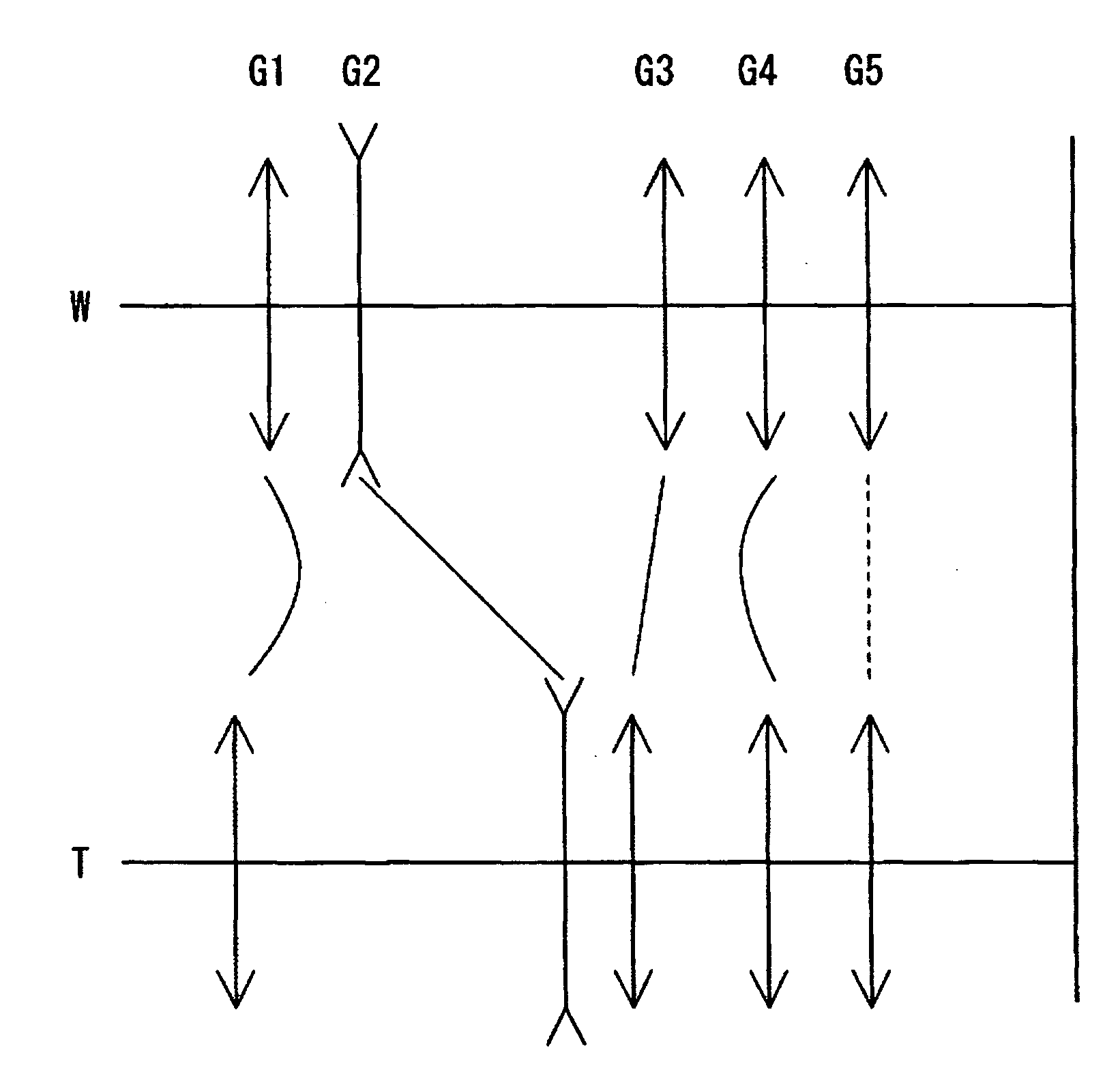
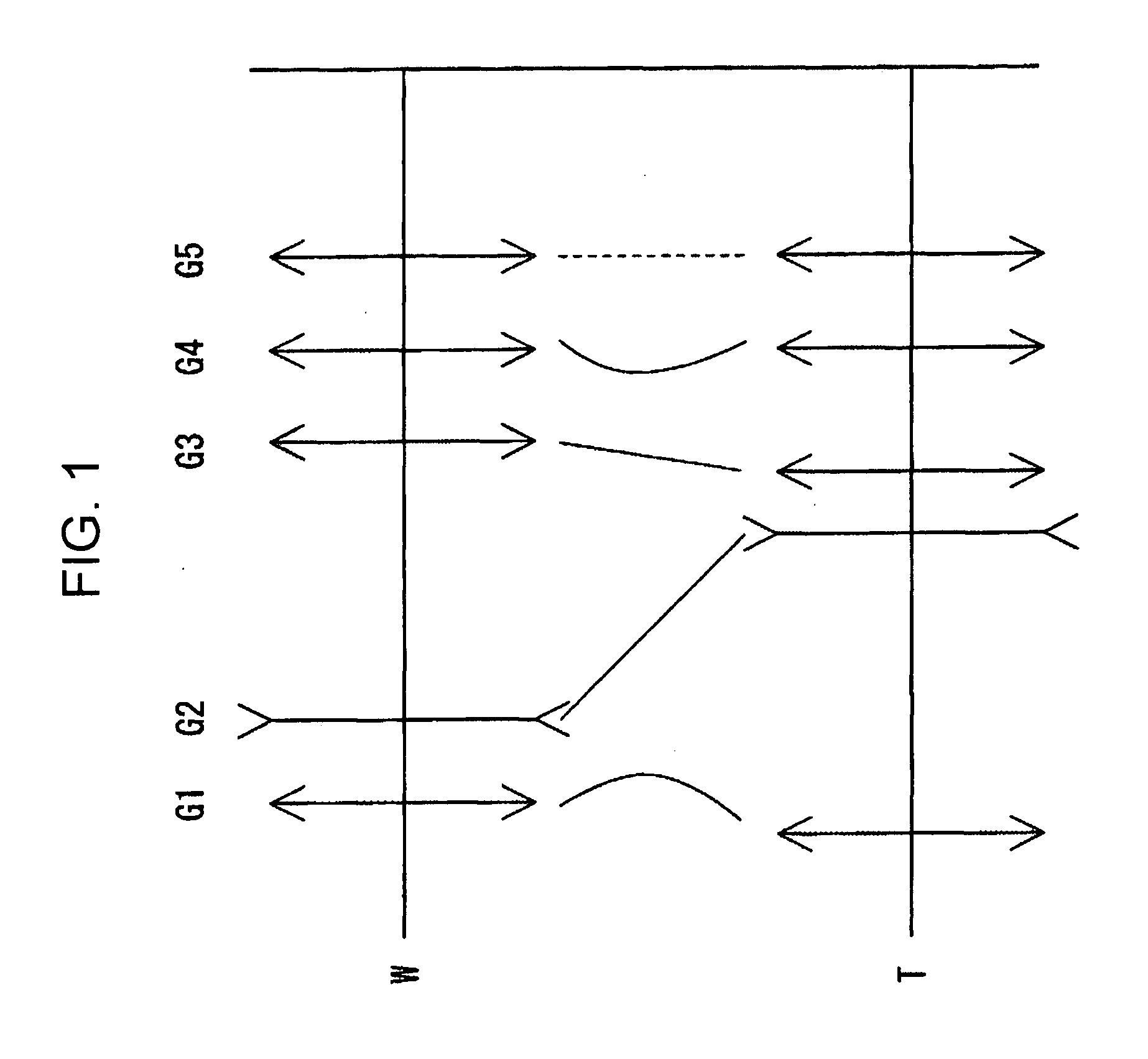
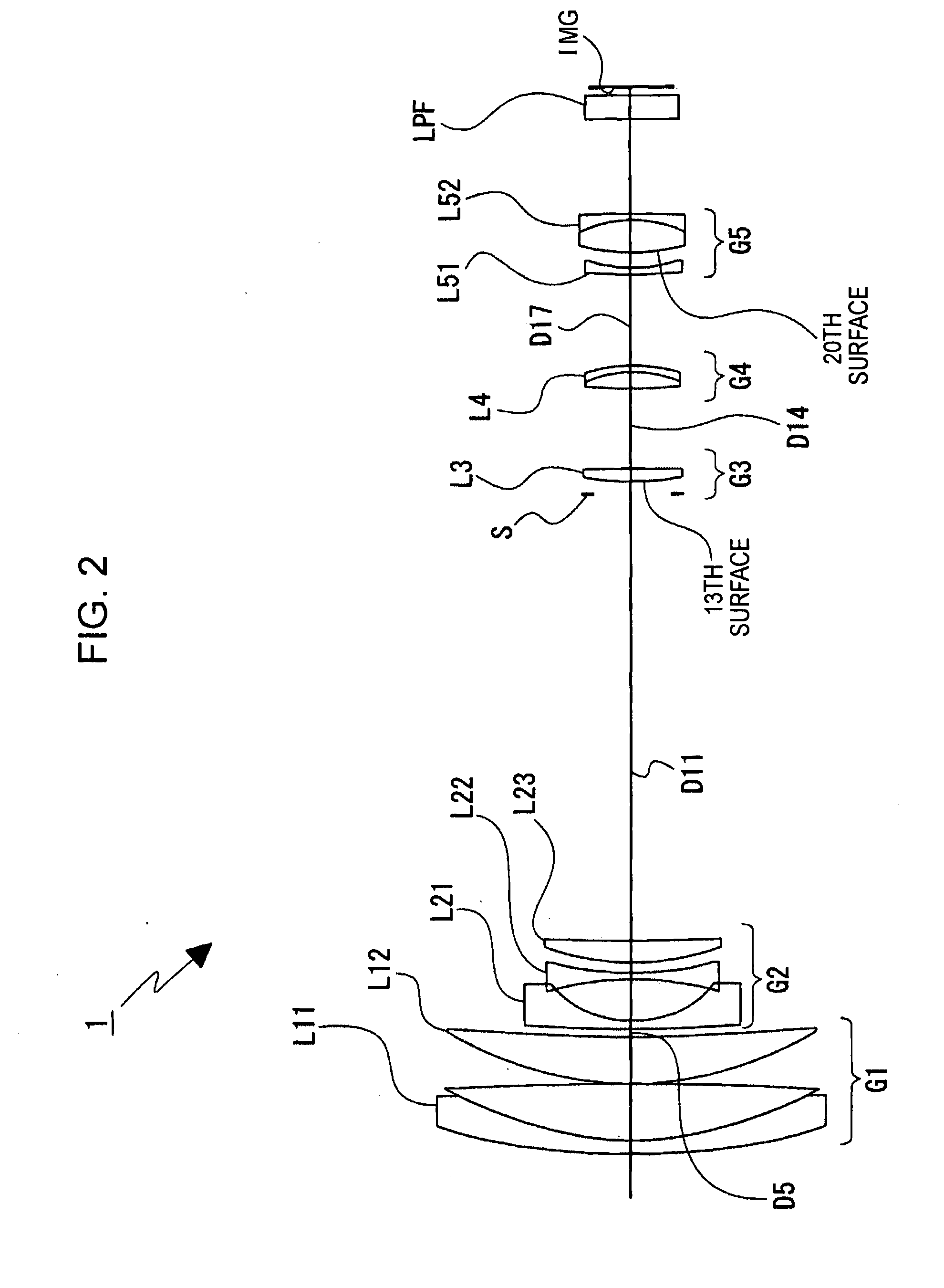
[0045] A zoom lens according to a first exemplary embodiment includes a first lens group having a positive refractive power, a second lens group having a negative refractive power, a third lens group having a positive refractive power, a fourth lens group having a positive refractive power, and a fifth lens group arranged in this order from the object side. When a lens zoom position is changed from a wide-angle position at which the focal length is minimum to a telephoto position at which the focal length is maximum, at least the first to fourth lens groups are movable. The second lens group is moved towards the image-plane side and the third lens group is moved towards the object side so that the distance between the first lens group and the second lens groups is increased and the distance between the second lens group and the third lens groups is decreased.

[0046] The fourth lens group is moved in the optical axis direction so as to compensate for the change in the position of the...

second exemplary embodiment

[0051] According to a second exemplary embodiment, a variable focal length lens system is similar to the variable focal length lens system according to the first exemplary embodiment. Let f5n denote the focal length of the negative subgroup included in the fifth lens group and fw denote the focal length of the whole lens system at the wide-angle position. Then, the variable focal length lens system further satisfies the following conditional expression:

2.5f5n| / fw<5  (2)

[0052] Thus, the performance can be further increased.

third exemplary embodiment

[0053] According to a third exemplary embodiment, a variable focal length lens system is similar to the variable focal length lens system according to the first embodiment or the second embodiment. However, the fifth lens group is stationary in the optical axis direction regardless of the lens zoom position. Thus, the lens barrel structure can be simplified.


PUM


Abstract

A variable focal length lens system includes first to fourth lens groups having positive, negative, positive, and positive powers, respectively, and a fifth lens group arranged in this order from an object side. When a lens zoom position is changed from a wide-angle to a telephoto, the first to fourth groups are movable and the second group is moved towards the image side and the third group is moved towards the object side so that a distance between the first and second groups increases and a distance between the second and third groups decreases, and the fourth group is moved along an optical axis direction so as to compensate for the positional change in the image plane. The fifth group includes a negative subgroup having negative power and a positive subgroup disposed on the image side of the negative subgroup and having positive power, and a predetermined condition is satisfied.

Description

CROSS REFERENCES TO RELATED APPLICATIONS [0001] The present invention contains subject matter related to Japanese Patent Application JP 2006-034905 filed in the Japanese Patent Office on Feb. 13, 2006, the entire contents of which are incorporated herein by reference. BACKGROUND OF THE INVENTION [0002] 1. Field of the Invention [0003] The present invention generally relates to a variable focal length lens system and an image capturing apparatus including the variable focal length lens system and, in particular, to a variable focal length lens system having a zoom ratio greater than 10 and an image capturing apparatus, such as a video camera or a digital still camera, including the variable focal length lens system. [0004] 2. Description of the Related Art [0005] To record a subject image in cameras, a method for recording the subject image by converting the intensity of light of the subject image to an electrical output using an image pickup device including photoelectric transducer...

Claims


Application Information

Patent Timeline
IPC IPC(8): G02B15/14
CPCG02B15/173G02B7/102G02B15/145129G02B15/145113G02B13/009G02B3/0087G03B17/12H04N23/55
Inventor OHTAKE, MOTOYUKI
Owner SONY CORP
Learn More