
Vibration proof zoom lens and photographing apparatus having the same

a technology of vibration proof and zoom lens, which is applied in the field of vibration proof zoom lens and photographing apparatus having the same, can solve the problems of large number of lenses, large even mass, and difficult control of the second lens group to move forward and rearward in very small amounts, and achieves the effect of improving the degree of freedom in refractive power setting, and reducing the number of lenses

Inactive Publication Date: 2015-09-22
SAMSUNG ELECTRONICS CO LTD
View PDF31 Cites 2 Cited by
  • Summary
  • Abstract
  • Description
  • Claims
  • Application Information

AI Technical Summary

Benefits of technology

The system achieves sufficient close distance with high variable-magnification and good optical performance, effectively supporting contrast detection type auto-focus by enabling precise control of focusing and vibration compensation, while simplifying the lens configuration and improving aberration correction.

Problems solved by technology

In the conventional vibration proof zoom lenses as described above, however, problems have been discovered, as follows:
In the zoom lenses, however, since the second lens group with the negative refractive power preceding the first lens group with the positive refractive power generally contributes to a major variable magnification among the entire optical system, it has a relatively large number of lenses, and is large even in mass.
On this account, there are problems in that it is difficult to control the second lens group to move forward and rearward in very small amounts and is not adapted to, particularly, a so-called contrast detection type auto focus by a blur detection of an image pickup device.
In the zoom lenses, however, since the third lens group is composed of three cemented lens, each of in which a positive lens, a positive lens and a negative lens are cemented with one another, there are problems in that this third lens group also has a relatively large number of lenses and is not adapted to, particularly, the so-called contrast detection type auto focus.

Method used


Image

  • Vibration proof zoom lens and photographing apparatus having the same
  • Vibration proof zoom lens and photographing apparatus having the same
  • Vibration proof zoom lens and photographing apparatus having the same

Examples


example

Example 1

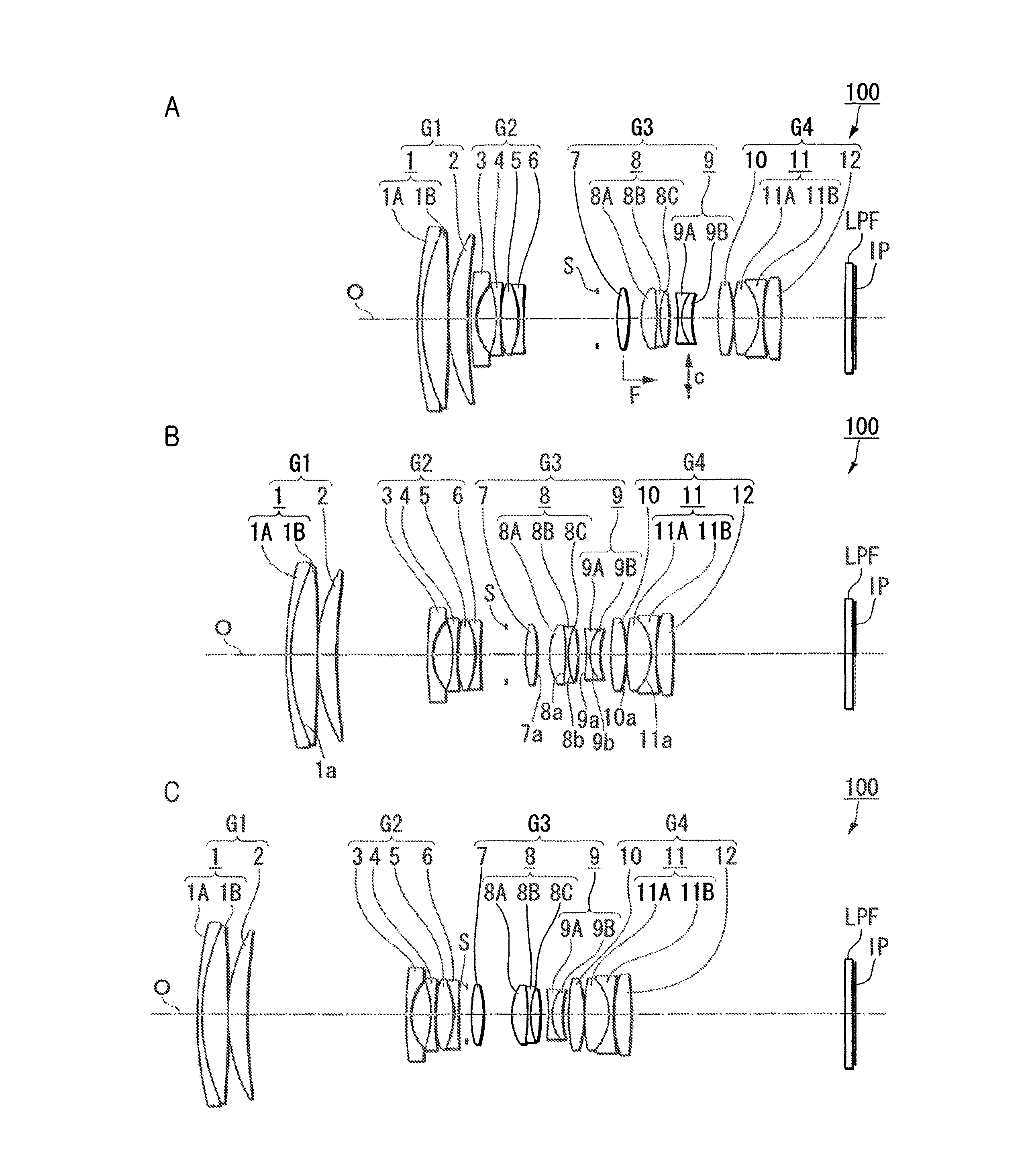
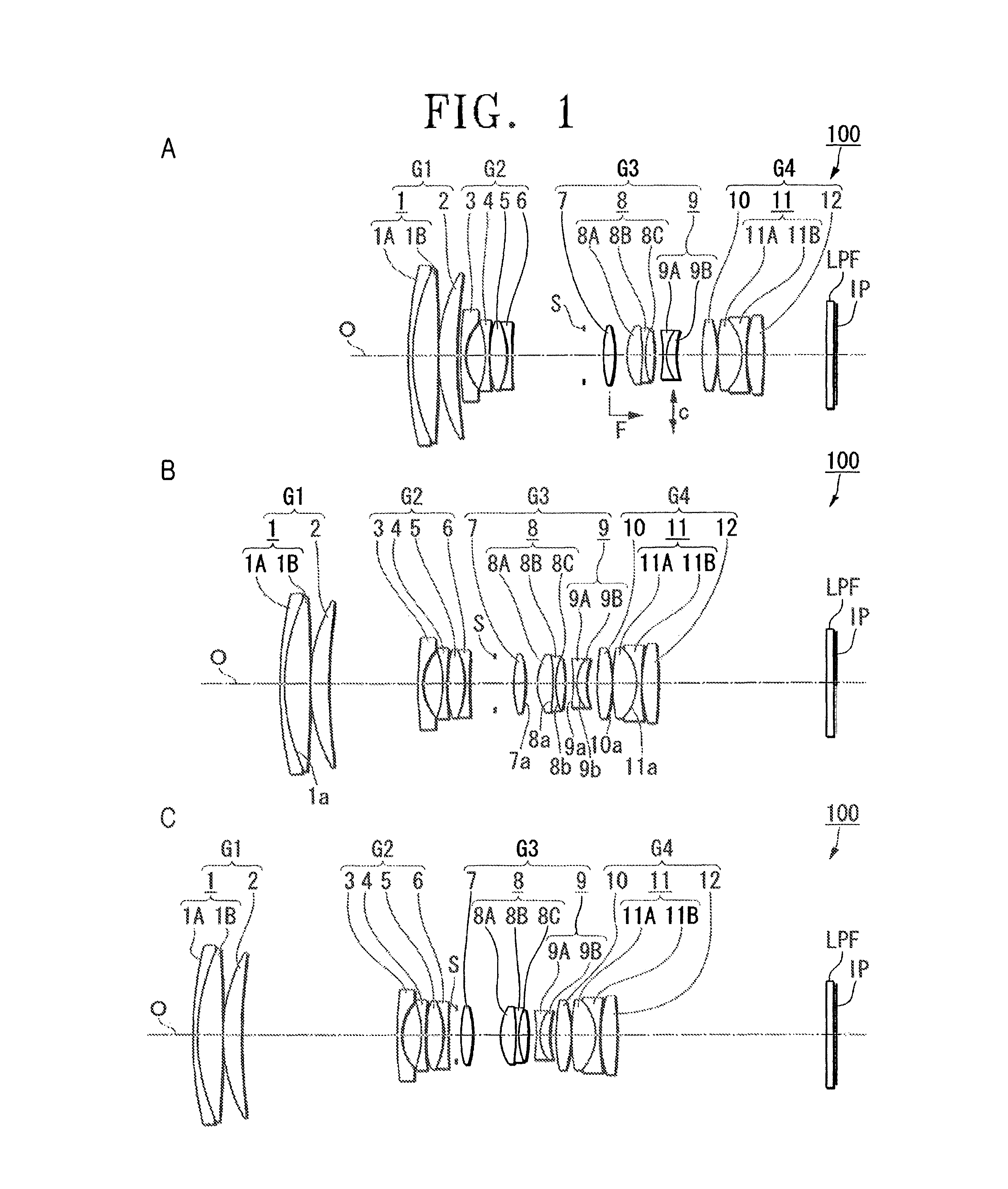
[0183]Next, an example 1, which is an example of a numerical value of the vibration proof zoom lens system 100 illustrated in the exemplary embodiment of FIGS. 1A-1C as described above will be explained.

[0184]The below table shows configuration parameters of the vibration proof zoom lens system 100 of the example 1. A surface number j (j is a natural number) is distributed to each of surfaces of lenses forming the vibration proof zoom lens system 100, respectively, so that the surface is increased toward the image side from a most object side lens surface to which a number 1 is assigned among surface of lenses forming the vibration proof zoom lens system 100.

[0185]Further, a radius of curvature Rj is a radius of curvature of the lens surface corresponding to the surface number j, a surface clearance Dj is a surface clearance on an axis between a lens surface of the surface number j and a lens surface of the surface number j+1, and units are mm. For instance, the cemented su...

example 2

[0200]Next, an example 2, which is an example of numerical value of the vibration proof zoom lens system 101 illustrated in the exemplary embodiment of FIGS. 3A-3C as described above will be explained.

[0201]The below table shows configuration parameters of the vibration proof zoom lens system 101 of the example 2. A surface number j (j is a natural number) is distributed in the same manner as in the example 1. For instance, the cemented surface 21a is a surface number 2, and the aspherical surface 27a is a surface number 18.

[0202]

Surface numberRadius of curvature(R)Surface clearance(D)refractive index(ηd)Abbe's number(νd)1R1 = 108.692D1 = 1.50η1 = 1.80518ν1 = 25.52R2 = 59.849D2 = 8.13η2 = 1.49700ν2 = 81.63R3 = −431.693D3 = 0.154R4 = 52.307D4 = 5.80η3 = 1.62041ν3 = 60.35R5 = 179.739D5 (Variable)6R6 = 141.166D6 = 1.30η4 = 1.83481ν4 = 42.77R7 = 13.905D7 = 5.968R8 = −32.856D8 = 1.10η5 = 1.83481ν5 = 42.79R9 = 68.778D9 = 0.1510R10 = 30.271D10 = 5.54η6 = 1.84666ν6 = 23.811R11 = −23.286D11 ...

example 3

[0208]Next, an example 3, which is an example of numerical value of the vibration proof zoom lens system 102 illustrated in the exemplary embodiment of FIGS. 4A-4C as described above will be explained.

[0209]The below table shows configuration parameters of the vibration proof zoom lens system 102 of the example 3. A surface number j (j is a natural number) is distributed in the same manner as in the example 1. For instance, the cemented surface 41a is a surface number 2, and the aspherical surface 47a is a surface number 18.

[0210]

Surface numberRadius of curvature(R)Surface clearance(D)refractive index(ηd)Abbe's number(νd)1R1 = 97.141D1 = 1.50η1 = 1.80518ν1 = 25.42R2 = 59.007D2 = 7.88η2 = 1.49700ν2 = 81.63R3 = −800.000D3 = 0.154R4 = 53.855D4 = 5.70η3 = 1.59282ν3 = 68.65R5 = 191.269D5 (Variable)6R6 = 142.685D6 = 1.30η4 = 1.83481ν4 = 42.77R7 = 14.165D7 = 6.198R8 = −38.401D8 = 1.10η5 = 1.83481ν5 = 42.79R9 = 56.480D9 = 0.1510R10 = 27.550D10 = 5.70η6 = 1.84666ν6 = 23.811R11 = −27.550D11 =...


PUM


Abstract

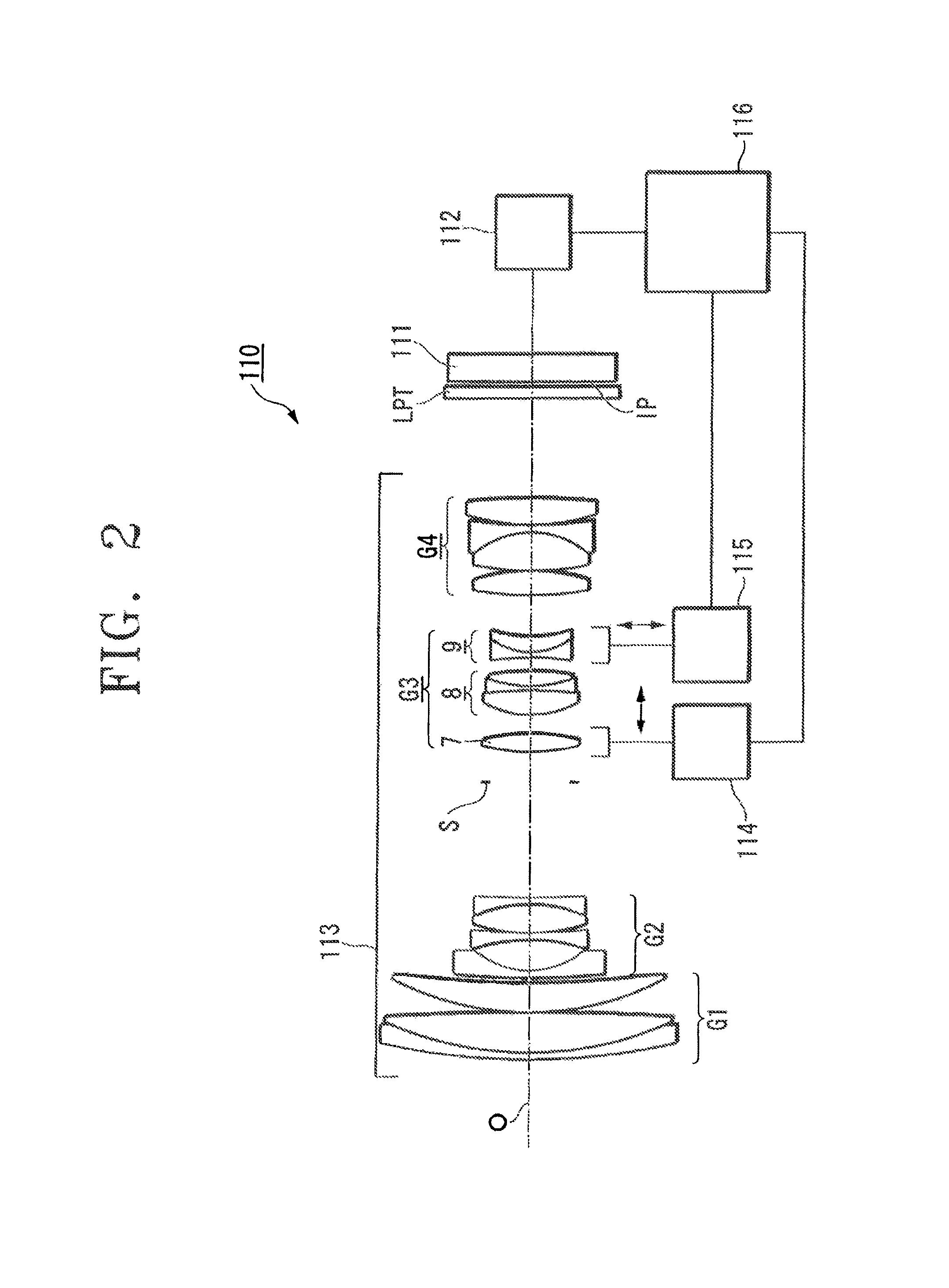
In a vibration proof zoom lens 100, a third lens group G3 has a positive lens 7, a positive cemented lens 8, a negative cemented lens 9, which are arranged in order from an object side. In variable-magnifying from a wide angle limit to a telephoto limit, a clearance between a first lens group G1 and a second lens group G2 is increased and at the same time, a clearance between the second lens group G2 and a third lens groupG3 is decreased, a focusing from an infinity side to a close side is performed by moving the positive lens 7 toward an image, and a vibration proof is performed by moving the cemented lens 9 in a direction perpendicular to an optical axis to change an image position.

Description

CROSS-REFERENCE TO RELATED APPLICATIONS[0001]This application claims priority from Japanese Patent Application No. 2010-284858, filed Dec. 21, 2010, in the Japan Intellectual Property Office, and Korean Patent Application No. 2011-0123237, filed on Nov. 23, 2011, in the Korean Intellectual Property Office, the disclosures of which are incorporated herein by reference in its entirety.BACKGROUND OF THE INVENTION[0002]1. Field of the Inventive Concept[0003]Apparatuses and methods consistent with the present inventive concept relate to a vibration proof zoom lens and a photographing apparatus having the same.[0004]2. Description of the Related Art[0005]There have been proposed various zoom lenses with a device (vibration-proofing apparatus) compensating for image shaking caused by vibrations fortuitously transmitted to a photographing system. For instance, there is known a zoom lens (vibration proof zoom lens), in which to compensate for the image shaking caused by the vibrations, moves...

Claims


Application Information

Patent Timeline
Patent Type & Authority Patents(United States)
IPC IPC(8): G02B27/64G02B15/173
CPCG02B27/646G02B15/173
Inventor MISAKA, MAKOTO
Owner SAMSUNG ELECTRONICS CO LTD
Learn More