Snowboard locking system

a technology for locking systems and snowboards, applied in the field of locking systems, can solve the problems of increasing the number of snowboard thefts, and the lack of racks with locks designed to temporarily hold snowboards while the user goes inside the ski lodge, and achieve the effect of sufficient width

Inactive Publication Date: 2001-07-24
KEMERY MIKE +1
View PDF22 Cites 49 Cited by
  • Summary
  • Abstract
  • Description
  • Claims
  • Application Information

AI Technical Summary

Benefits of technology

It is a further object of the invention to provide such a snowboard locking system that can be used with all snowboard designs to prevent theft when left unattended and does not require modification to the snowboard itself.
These and other objects are met by a snowboard locking system that uses two rigid elongated members that, during use, are transversely aligned and extended across opposite sides of a snowboard and then locked in position around the snowboard. Each elongated member includes a U-shaped element having sufficient width to engage the outer edge of a snowboard, at least one first leg component having sufficient length to extend at least one-half way across a snowboard, and a second leg component parallel to the first leg component having sufficient length to engage the opposite side of the snowboard and prevent movement of the elongated member perpendicular to the top or bottom surfaces of the snowboard. During use, the ends of the first leg components are locked together to prevent the elongated members from sliding transversely apart and being removed from the snowboard.

Problems solved by technology

With this growth, the number of snowboard thefts is also increasing.
Because snowboarding is a relatively new sport, racks with locks designed to temporarily hold a snowboard while the user goes inside the ski lodge are not widely available.

Method used


Image

  • Snowboard locking system
  • Snowboard locking system
  • Snowboard locking system

Examples


Embodiment Construction

)

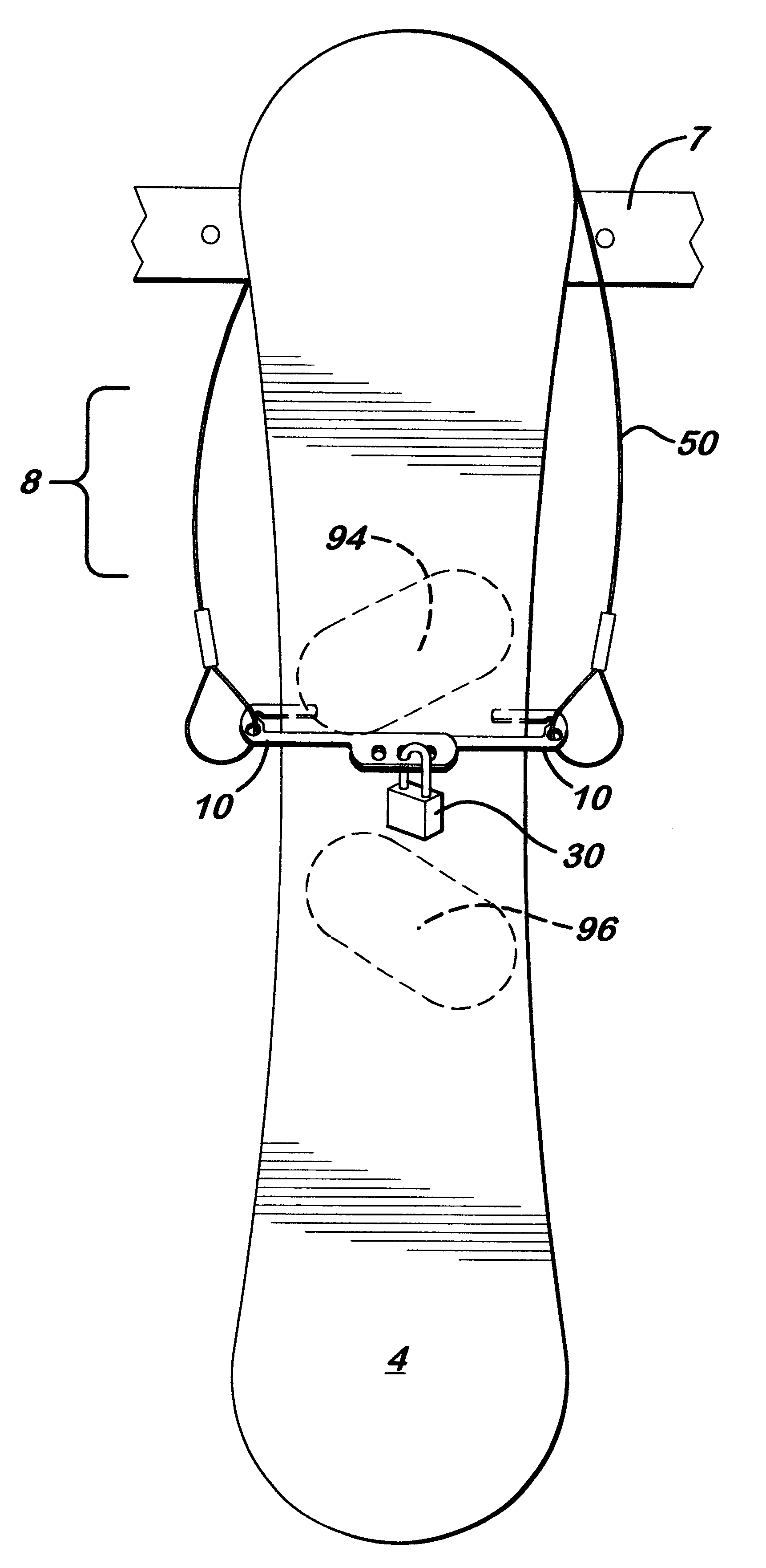
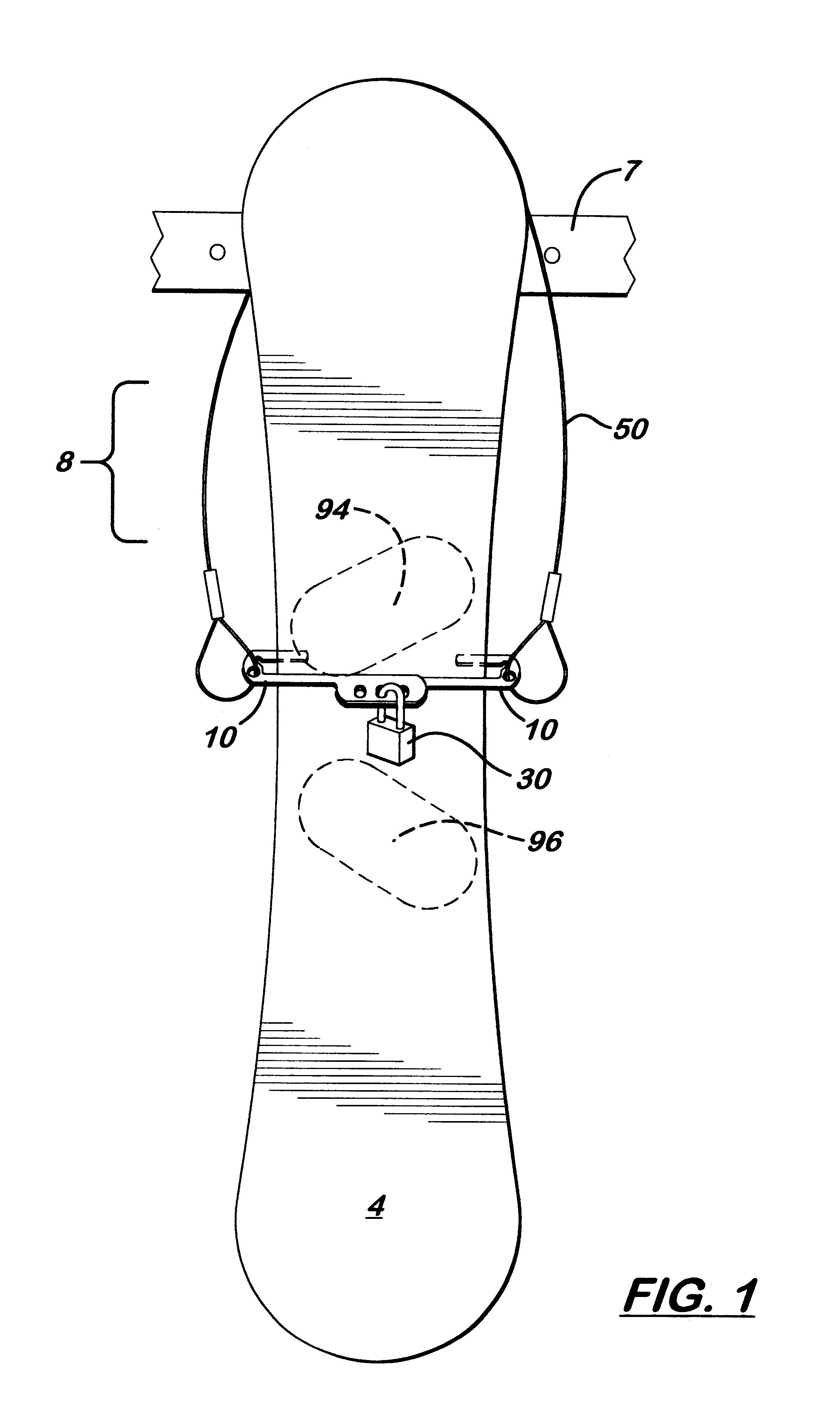
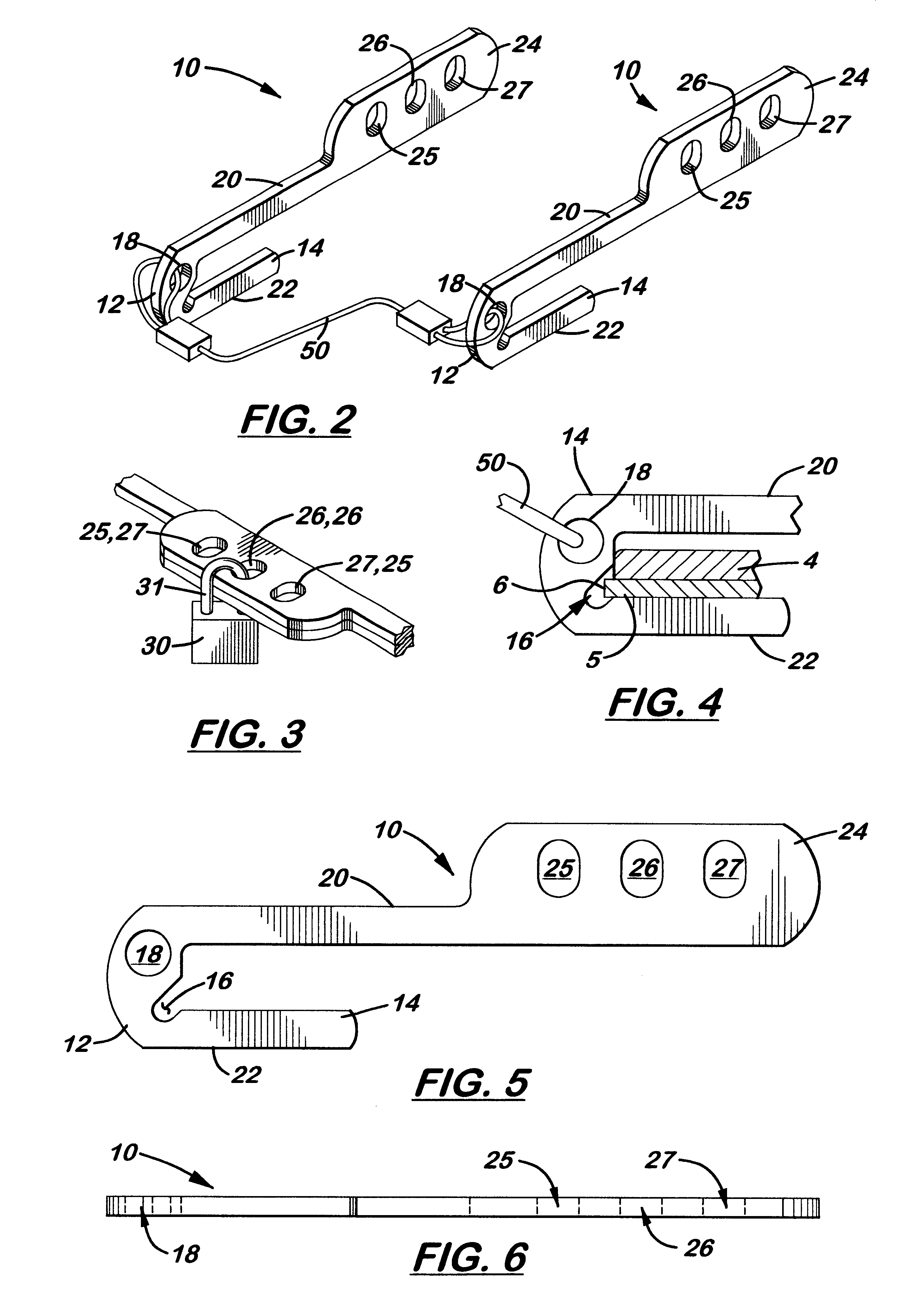
Referring to the accompanying FIGS. 1-8, wherein like reference numbers denote like components, there is shown a lightweight, compact snowboard binding system 8. The system 8 is designed to be selectively attached to a snowboard 4 to prevent its operation if stolen. It is also designed to be selectively attached to a fixed object to prevent its removal therefrom.

In the first embodiment, the system 8 includes two elongated members 10 that, during installation, are transversely aligned and extended across one surface from opposite sides of a snowboard 4. Each elongated member 10 is designed to extend transversely approximately 2 / 3 the width of a standard snowboard 4 at the mid-line axis of the snowboard 4. Each elongated member 10 includes a U-shaped element 14 with one parallel, integrally formed first leg component 20 and one second leg component 22. As shown in FIG. 4, the U-shaped element 14 is designed to receive the outer edge 5 of the snowboard 4 when the elongated member 10 i...


PUM


Abstract

A snowboard locking system including two longitudinal members that are transversely aligned and partially overlapping from opposite sides of the middle section of a snowboard. Each elongated member includes a U-shaped portion designed to capture the outer edge of the snowboard when the elongated member is transversely aligned thereover. Formed on the end of each elongated member opposite the U-shaped portion is a wide body portion with a plurality of holes formed thereon. During installation on a snowboard, the elongated members are transversely aligned on opposite sides of the snowboard so that the U-shaped portions capture the opposite outer edges of the snowboard and the body portions overlap. A plurality of holes formed on the body portion of each elongated member may be aligned and registered. A lock extending through the aligned holes of the two elongated members is then used to hold them in a transversely aligned position on the snowboard. An optional cable is also provided that permanently attaches to the distal ends of each elongated member. During use, the cable may be looped around a fixed, stationary object to attach the snowboard to the object.

Description

1. Field of the InventionThis invention relates to locking systems, and, more specifically, to portable locking systems for snowboards.2. Description of the Related ArtSnowboards are growing in popularity. With this growth, the number of snowboard thefts is also increasing.Because snowboarding is a relatively new sport, racks with locks designed to temporarily hold a snowboard while the user goes inside the ski lodge are not widely available. Therefore, portable locking systems for snowboards would be very useful.Ideally, the locking system for a snowboard should be lightweight and compact so that it can be transported by the user while snowboarding. The system should also be easily and quickly attachable to the snowboard to prevent use of the snowboard and to prevent or at least deter theft when left unattended. The system should be capable of being used with most snowboard designs without requiring modification to the snowboard itself.It is an object of the present invention to pr...

Claims


Application Information

Patent Timeline
Patent Type & Authority Patents(United States)
IPC IPC(8): A63C11/00E05B73/00E05B37/00E05B37/02
CPCA63C11/006E05B73/0005E05B73/007E05B37/025Y10T70/409Y10T70/411Y10T70/40Y10T70/5009
Inventor KEMERY, MIKEKAPFHAMMER, ERIC
Owner KEMERY MIKE
Why Eureka
Try Eureka