Electromagnetic flowmeter deriving power from signalling loop current

a technology of signalling loop current and flowmeter, which is applied in the direction of fluid speed measurement, measurement devices, instruments, etc., can solve the problems of complicated control circuits, high cost of flowmeter, and severe power constraints of such flowmeters

Inactive Publication Date: 2001-08-07
ABB KENT TAYLOR
View PDF11 Cites 45 Cited by
  • Summary
  • Abstract
  • Description
  • Claims
  • Application Information

AI Technical Summary

Problems solved by technology

The power constraints in such a flowmeter are very severe, however.
This requires complicated control circuitry, adding to the cost of the flowmeter.
This however would allow only about 40 mW to operate the sensor at low flow rates, and the above described proposal may not function reliably at such low power levels.
This disadvantage is compounded, as the inventor has realised, by the fact that it is particularly when the flow rate is lowest that it is most difficult to obtain reliable measurements with a high signal-to-noise ratio; the signal generated by such a flowmeter is generally proportional to the coil current applied to the coil and to the flow velocity, and at low velocities, the

Method used


Image

  • Electromagnetic flowmeter deriving power from signalling loop current
  • Electromagnetic flowmeter deriving power from signalling loop current
  • Electromagnetic flowmeter deriving power from signalling loop current

Examples


Embodiment Construction

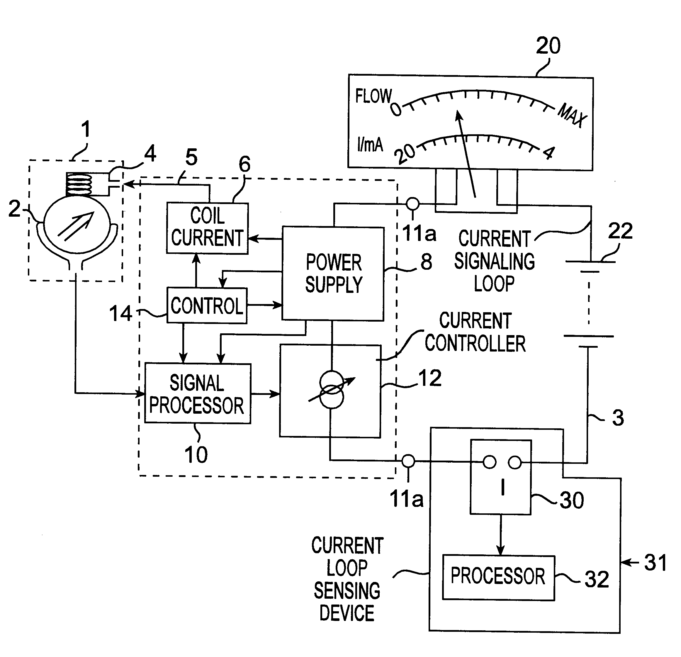
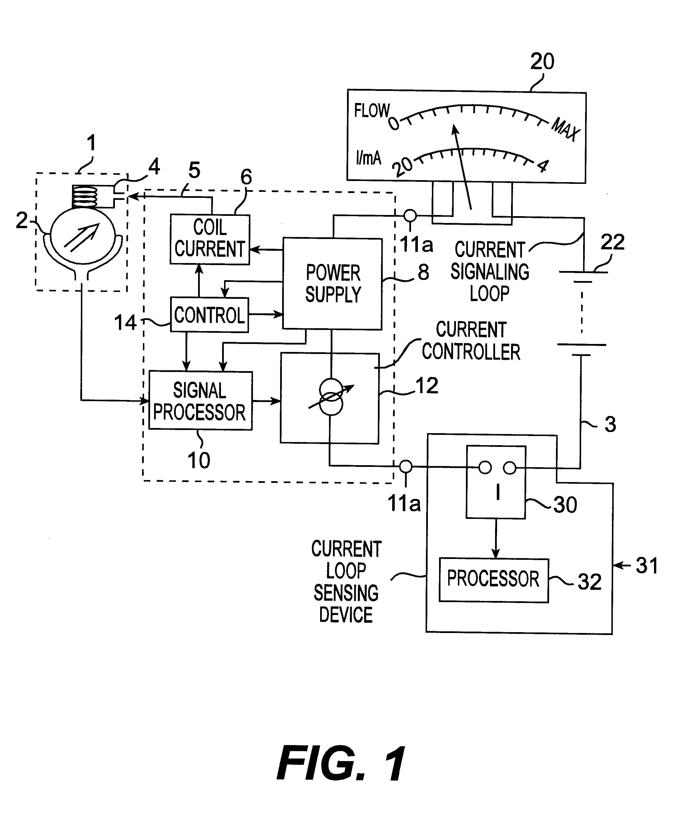
Referring now to the drawing, a flowmeter sensor 1 is located in the path of fluid along a pipeline (not shown). The probe senses a voltage induced in electrodes 2 across the fluid in response to a magnetic field generated in the fluid by means of a coil 4. The coil is supplied with a controlled coil current 5 from coil current supply 6, which in turn derives power from a power supply unit 8 which derives power from the current signalling loop 3 which flows between two terminals 11a and 11b of the flowmeter. The power supply 8 also provides power to the other components, to be described below. Not shown, a battery may be included in the power supply 8 to supplement the power available from the current signalling loop 3; in such a case, the life of the battery will be considerably extended, or its capacity may be reduced, by making use of the power available from the current signalling loop 3. Preferably, however, all power required for normal operation of the flowmeter is drawn from...


PUM


Abstract

An improvement over conventional electromagnetic flowmeters which signal a measure of flow rate by controlling the current in a current signalling loop (also known as a sensing loop) and in which power for the flowmeter is derived from the current in the signalling/sensing loop. Conventional electromagnetic flowmeters use a standard current range (typically 4-20 mA), in which zero flow is indicated by controlling the current in the loop to a minimum predeterimened value and maximum flow is indicated by controlling the current to a maximum predetermined value. In the improved flowmeter of the invention, minimum flow is signalled by maximum current in the signalling/sensing loop and maximum flow is signalled by minimum current. This has been found to enable improved accuracy to be obtained at low flow rates without requiring complex flowmeter circuitry.

Description

1. Field of the InventionThe preset application relates to electromagnetic flowmeters. Electromagnetic flowmeters are used in a variety of applications. As is well known, they operate by providing a current to a coil to generate a magnetic field in the fluid to be monitored, and detecting a voltage, generated across the fluid, which is generally proportional to the product of the magnetic field strength and the flow velocity.2. Description of Prior ArtA common method of signalling the flow rate is for the flowmeters to control the current flowing in a current signalling loop (also sometimes referred to as a_sensing loop or simply a current loop), the magnitude of the current in the current sensing loop_indicating the rate of fluid flow, the current being arranged to flow in a current signalling_loop incorporating a display or other metering apparatus remote from the sensor probe of the flowmeter. Commonly, a current output in the current signalling loop in the range of 4-20 mA is us...

Claims


Application Information

Patent Timeline
IPC IPC(8): G01F1/56G01F1/60
CPCG01F1/60
Inventor KEECH, RAY
Owner ABB KENT TAYLOR
Why Eureka
Try Eureka