Dust collector with air flow adjusting device on up flow of motor

A technology of regulating device and vacuum cleaner, applied in the direction of vacuum cleaner, flow control, control/regulation system, etc., can solve the problems of reducing air flow, increasing negative pressure, reducing suction quality, etc.

Inactive Publication Date: 2008-04-02
SEB SA
View PDF0 Cites 1 Cited by
  • Summary
  • Abstract
  • Description
  • Claims
  • Application Information

AI Technical Summary

Problems solved by technology

[0005] [05] In fact, when the garbage collection bag is blocked, it is difficult for air to pass through said collection bag...

Method used


Image

  • Dust collector with air flow adjusting device on up flow of motor
  • Dust collector with air flow adjusting device on up flow of motor
  • Dust collector with air flow adjusting device on up flow of motor

Examples


Embodiment Construction

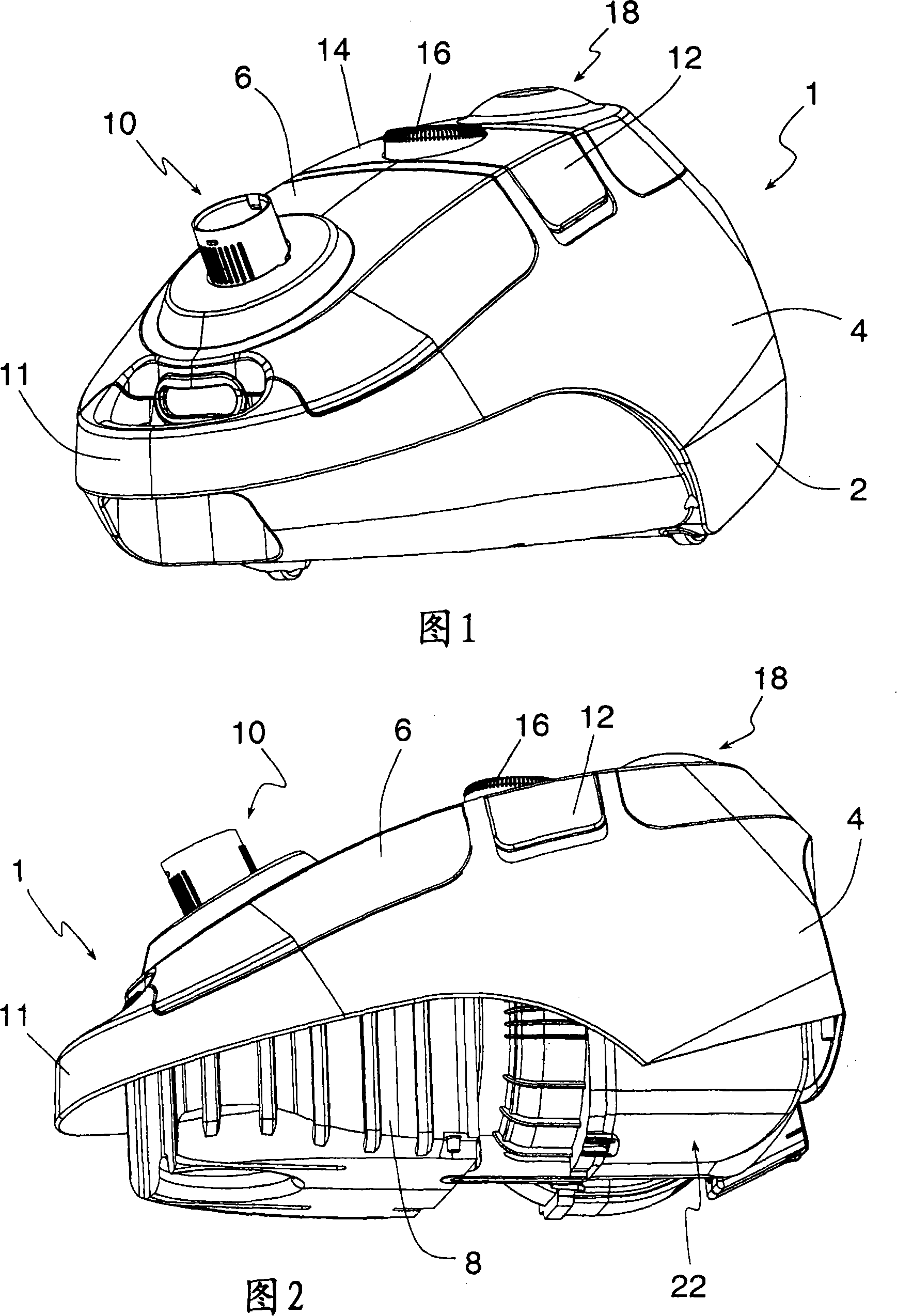
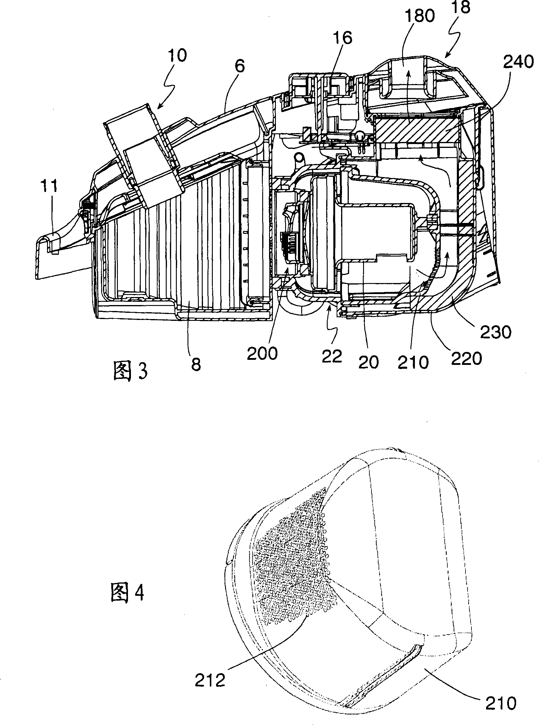
[0039] [39] As shown in Figures 1-3, the vacuum cleaner 1 is composed of a vacuum cleaner main body, which is composed of a lower body 2, an upper body 4 and a cover 6, and the cover 6 closes the groove 8 of the vacuum cleaner bag. The rear surface of the slot 8 includes openings in air communication with the motor chamber.

[0040] [40] The cover 6 is also provided with a connection 10 that can connect the suction pipe to the storage bag for the air filter and suction waste. The circular portion of the front of the upper body forms the handle 11 .

[0041] [41] The upper body 4 is also provided with mechanisms 12, 14 and 16 for respectively controlling the start and stop of the motor, the winding of the electric wire and the power of the motor. Bleeding of air from the motor is achieved through an assembly 18 located on the upper body 4 at the rear of the device.

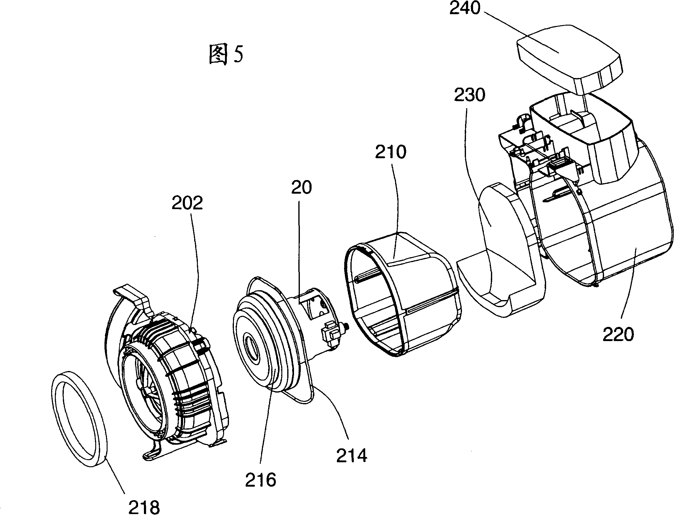
[0042] [42] The vacuum cleaner motor 20 is located in a fairing 22 connected to the air outlet opening of the ...


PUM


Abstract

The present invention relates to a dust collector (1) which comprises a frame provided with an electric motor (20) connected with a fan. When the dust collector is running, at the upstream of the electric motor (20), air suction can be generated from one pipeline to a suction nozzle and to the air outlet of the frame at the downstream of the electric motor (20). A filter device is arranged on the pneumatic power path and is preferably arranged on the upstream of the motor (20). Regulating devices (200, 400) for regulating the air flux in the dust collector (1) are arranged on the pneumatic power path at the upstream of the motor (20). When the motor (20) is operating, the regulating devices (200, 400) can cause the change to the air flow area passing through under the condition that the flux is changed. The dust collector is characterized in that the change of the air flow area can be realized in a range from 80% to 100% of the predetermined maximum flux.

Description

technical field [0001] [01] The present invention relates to the field of vacuum cleaner household appliances, in particular to the structure of the vacuum cleaner. [0002] [02] The object of the present invention is to propose a device that can automatically adjust the flow rate of the vacuum cleaner. [0003] [03] More particularly, the object of the present invention is to limit the maximum flow rate of the vacuum cleaner in order to limit the noise of the vacuum cleaner and at the same time reduce the clogging speed of the filter, which will ensure a large effective power. [0004] [04] The object of the invention is also to limit flow fluctuations in the pneumatic suction chain, such fluctuations may be associated with clogging of the collection bag, for example. Background technique [0005] [05] In fact, when the waste collection bag is blocked, it is difficult for the air to pass through said collection bag, thus reducing the air flow, and increasing the negative p...

Claims


Application Information

Patent Timeline
IPC IPC(8): A47L5/12G05D7/00
CPCA47L9/0072
Inventor 法比安·达维德埃里克·马沙尔
Owner SEB SA
Why Eureka
Try Eureka