Improved applicability of lamps with electronic ballast without a protective earth conductor

A technology for electronic ballasts and illuminants, applied in the field of illuminants, can solve the problems of reducing electromagnetic compatibility contact voltage and other issues

Inactive Publication Date: 2013-05-08
OSRAM GMBH
View PDF0 Cites 0 Cited by
  • Summary
  • Abstract
  • Description
  • Claims
  • Application Information

AI Technical Summary

Problems solved by technology

If such illuminants are operated without a lead wire (PE conductor) to protective earth, such illuminants may have reduced electromagnetic compatibility (EMV) or increased contact voltage, or they may cause failure of the EVG

Method used


Image

  • Improved applicability of lamps with electronic ballast without a protective earth conductor
  • Improved applicability of lamps with electronic ballast without a protective earth conductor
  • Improved applicability of lamps with electronic ballast without a protective earth conductor

Examples


Embodiment Construction

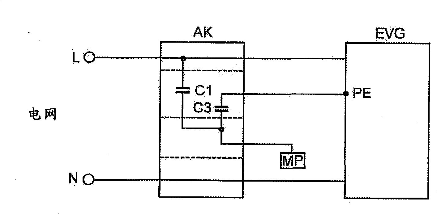
[0048] exist figure 1 The wiring of the circuit according to the invention in the luminaire is shown in a highly schematic block diagram in . Shown on the left is the grid terminal with the phase conductor L and the neutral conductor N, which is led to the illuminant connection terminal AK via a grid lead that is not further separated. The illuminant connection AK is a uniform plastic housing (shown by a rectangle) with the known per se embedded terminal contacts for the lines L and N, but without a PE connection contact. Capacitors C1 and C3 are Y-capacitors with a capacitance of 2.2nF or 1.5nF. The protective ground terminal PE of the EVG is connected to the isolated conductive luminous body part MP (such as the connection contact part of the housing, the metal reflector or the mounting piece or the mounting plate) through the capacitor C3. Two capacitors are held in the light connection terminals. The line between the capacitor C3 and the mounting plate MP can be constit...


PUM


Abstract

The invention relates to improving the electromagnetic compatibility for lamps with integrated electronic ballast which are operated without a protective earth supply line, and involves capacitively coupling the electronic ballast housing to insulated conductive parts of the lamp by means of a capacitor (C3), possibly in conjunction with a further capacitor (C1) for fixing the touch voltage, and a radio frequency-absorbing damping element (F).

Description

technical field [0001] The invention relates to a luminaire with an integrated electronic ballast (EVG). Background technique [0002] The term "luminaire" refers to a lighting device designed for the installation of a lamp or a lighting device already containing a mounted lamp which, in addition to the lamp, has a housing, a bracket or a reflector for the lamp as well as for the grid Connecting terminals for conductors. The term "lamp" here refers to a lighting device, for example a discharge lamp or a halogen incandescent lamp or an LED or an LED module. [0003] In this case, the invention only relates to illuminants which contain an integrated electronic ballast with a protective earth connection. If such illuminants are operated without a protectively earthed conductor (PE conductor), such illuminants may have reduced electromagnetic compatibility (EMV) or increased contact voltages, or they may cause malfunctions of the EVG. Contents of the invention [0004] The ...

Claims


Application Information

Patent Timeline
Patent Type & Authority Patents(China)
IPC IPC(8): H05B41/285
CPCH05B41/2851
Inventor 赖因哈德·莱谢勒西格弗里德·迈尔
Owner OSRAM GMBH
Why Eureka
Try Eureka