Method for continuously determining air-actuated compression release valve flow characteristic

A technology of flow characteristics and pressure reducing valve, applied in the direction of measuring devices, testing of mechanical parts, testing of machine/structural parts, etc. Test efficiency, cost savings of test equipment, ease of use and promotion

Inactive Publication Date: 2009-12-23
BEIJING INSTITUTE OF TECHNOLOGYGY
View PDF2 Cites 2 Cited by
  • Summary
  • Abstract
  • Description
  • Claims
  • Application Information

AI Technical Summary

Problems solved by technology

Therefore there are the following problems: 1) the complexity of the test device and the circuit is easy to cause the low test efficiency and the increase of the test cost; 2) when the test circuit is replaced, it is easy to produce a measurement error at the zero point of the flow due to the replacement of the measuring instrument; 3) Difficult to automate testing
Although the loops of the two test processes can be combined by adding a stop valve in the loop, it increases the complexity of the loop, thereby increasing the cost of the test and reducing the practicality of the experiment

Method used


Image

  • Method for continuously determining air-actuated compression release valve flow characteristic
  • Method for continuously determining air-actuated compression release valve flow characteristic
  • Method for continuously determining air-actuated compression release valve flow characteristic

Examples


Embodiment Construction

[0039] The present invention will be further described below in conjunction with drawings and embodiments.

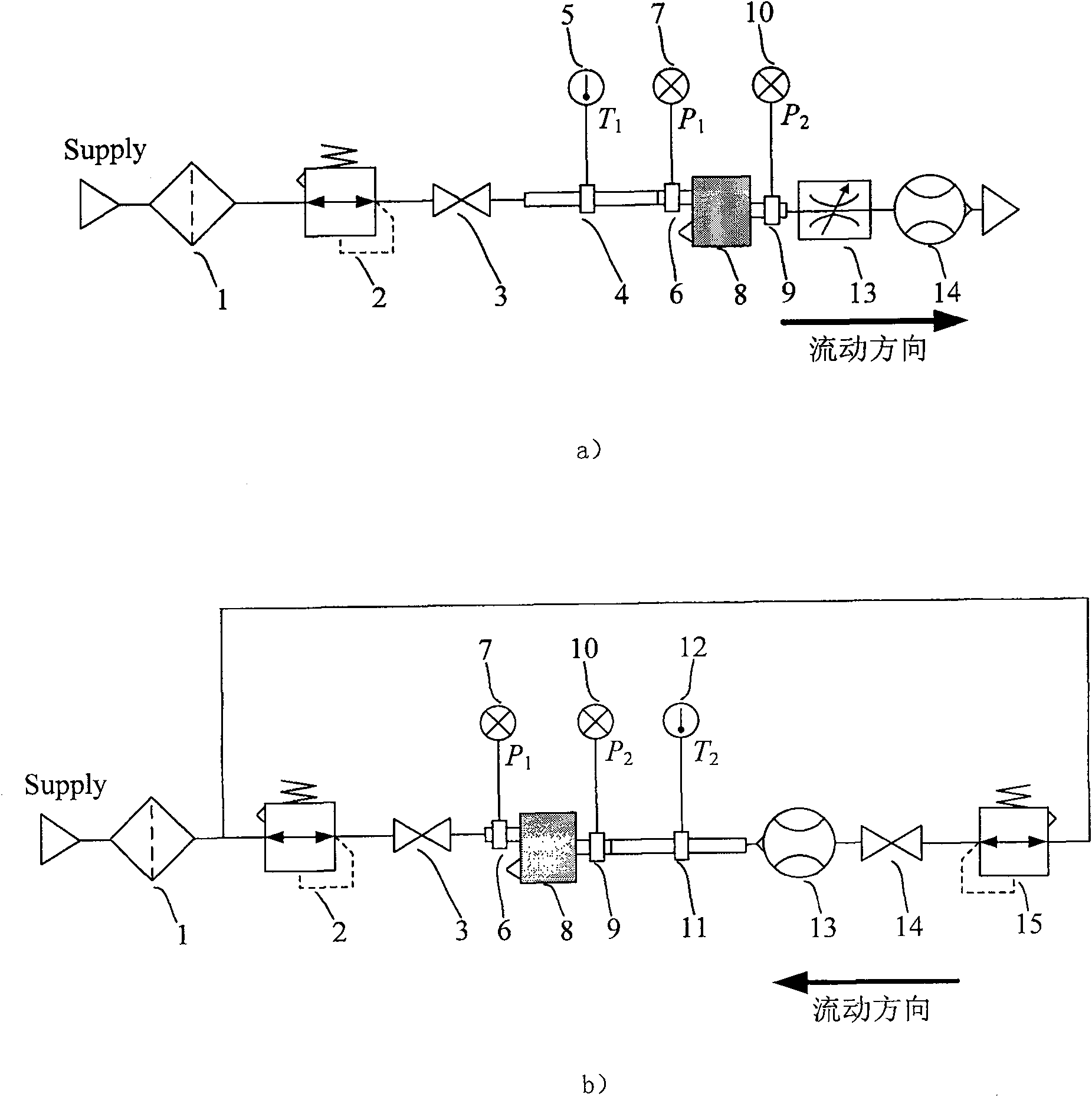
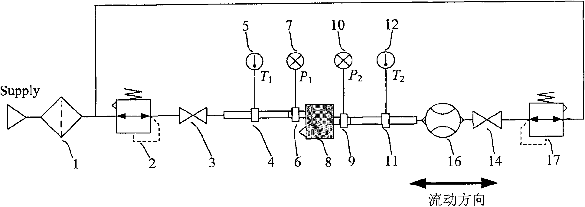
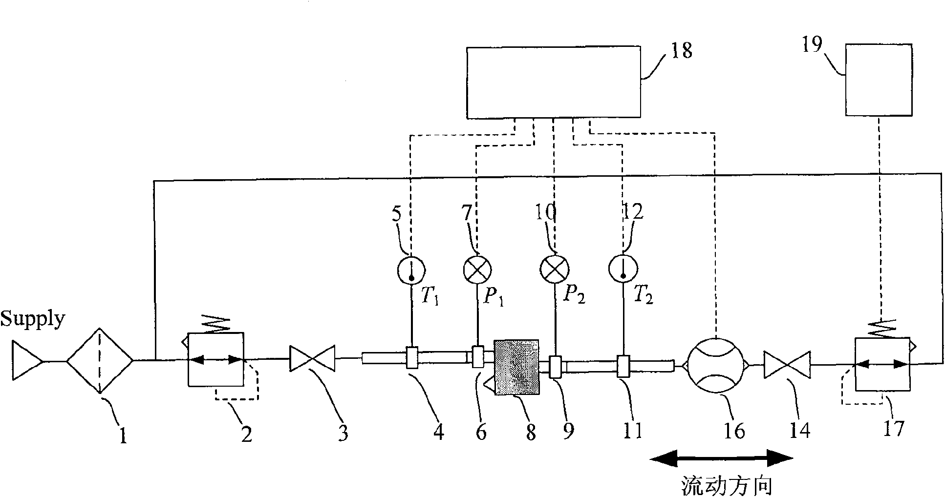
[0040] Such as figure 2 As shown, the experimental device of the present invention is mainly composed of a filter 1, an air supply pressure setting pressure reducing valve 2, an air supply side stop valve 3, an air supply side and a control side temperature measuring tube 4, 11, an air supply side and a control side Pressure measuring tubes 6 and 9, tested pressure reducing valve 8, bidirectional flowmeter 16, control side stop valve 14, control side pressure reducing valve 17; the air supply end of the measured pressure reducing valve 8 passes through pressure measuring tube 6, and the temperature is measured The pipe 4 is connected to the outlet of the air supply pressure setting pressure reducing valve 2, the control end of the measured pressure reducing valve 8 passes through the pressure measuring tube 9, the temperature measuring tube 11 is connected to the forwa...


PUM


Abstract

The invention relates to a device and method for continuous measurement of flow characteristics of a pneumatic pressure reducing valve. The device mainly includes: filter, air supply pressure setting pressure reducing valve, air supply side stop valve, air supply side temperature measuring tube, control side temperature measuring tube, air supply side pressure measuring tube, control side pressure measuring tube, Measure pressure reducing valve, bi-directional flowmeter, control side stop valve and control side pressure reducing valve; The flow measurement function realizes continuous measurement of pressure and flow through uninterrupted manual or automatic setting from the positive maximum flow to the overflow to the maximum flow, so as to measure the control port flow and control port pressure of the pressure reducing valve under test. Relationship, that is, the flow characteristics of the pressure reducing valve under test. The invention simplifies the experimental circuit, reduces the exchange of test equipment and the measurement error generated, improves the test efficiency and saves the air consumption.

Description

technical field [0001] The invention relates to a manual or automatic device for uninterrupted and continuous measurement of the flow characteristics of a pneumatic pressure reducing valve. The pressure or flow at the control end of the pressure reducing valve to be tested is adjusted through the pressure reducing valve with a large overflow function, and the device with The flow meter with bi-directional flow measurement function can realize continuous and uninterrupted measurement of flow characteristics from the forward flow stage to the overflow flow stage. Background technique [0002] Pneumatic pressure control valve is an important pressure control element in the field of automation technology. The most important performance index affecting the control system is the pressure-flow characteristic, that is, the change characteristic of the control pressure within the control flow range. Therefore, measuring its pressure and flow characteristics correctly and efficiently ...

Claims


Application Information

Patent Timeline
Patent Type & Authority Patents(China)
IPC IPC(8): G01M13/00
Inventor 王涛彭光正香川利春
Owner BEIJING INSTITUTE OF TECHNOLOGYGY
Why Eureka
Try Eureka