
Automotive full locking differential

a full locking differential and differential technology, applied in the direction of magnetically actuated clutches, mechanical equipment, gearing, etc., can solve the problems of large traction problems, open differentials, and only provide limited power in marginal traction situations, so as to achieve simple, effective and smooth operation.

Inactive Publication Date: 2001-08-07
ZENTMYER JOHN
View PDF3 Cites 167 Cited by
  • Summary
  • Abstract
  • Description
  • Claims
  • Application Information

AI Technical Summary

Benefits of technology

It is the primary object of the present invention to provide a locking differential that is simple, effective and smooth in its operation.

Problems solved by technology

Differentials go back to the beginnings of the automotive era, but many of them had major traction problems in difficult terrain.
However, open differentials have one major drawback: They can provide only limited power in marginal traction situations.
Other types of traction-enhancing devices and systems also have been developed, notably viscous coupling differentials and electronic traction control (ETC); however, these and other exotic designs are not mechanical lockers.
While many of them have been satisfactory in many respects, they also have some drawbacks.
Among these drawbacks are complexity, lack of reliability, cost, and adverse vehicle handling characteristics.

Method used


Image

  • Automotive full locking differential
  • Automotive full locking differential
  • Automotive full locking differential

Examples


Embodiment Construction

The above and other objects and advantages of the present invention will become apparent from the following description when read in conjunction with the accompanying drawings wherein:

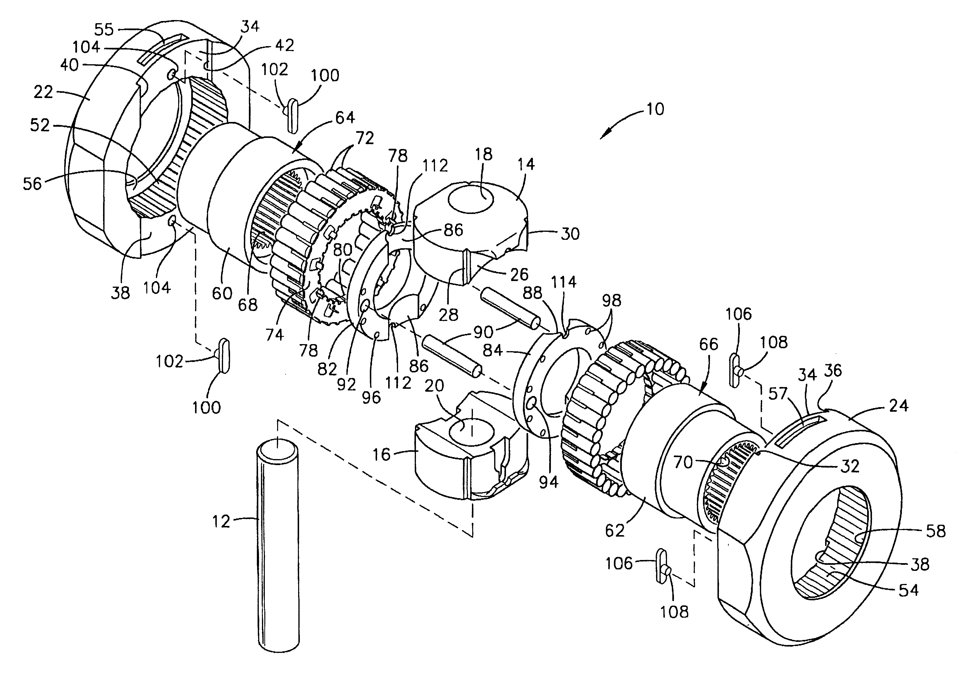
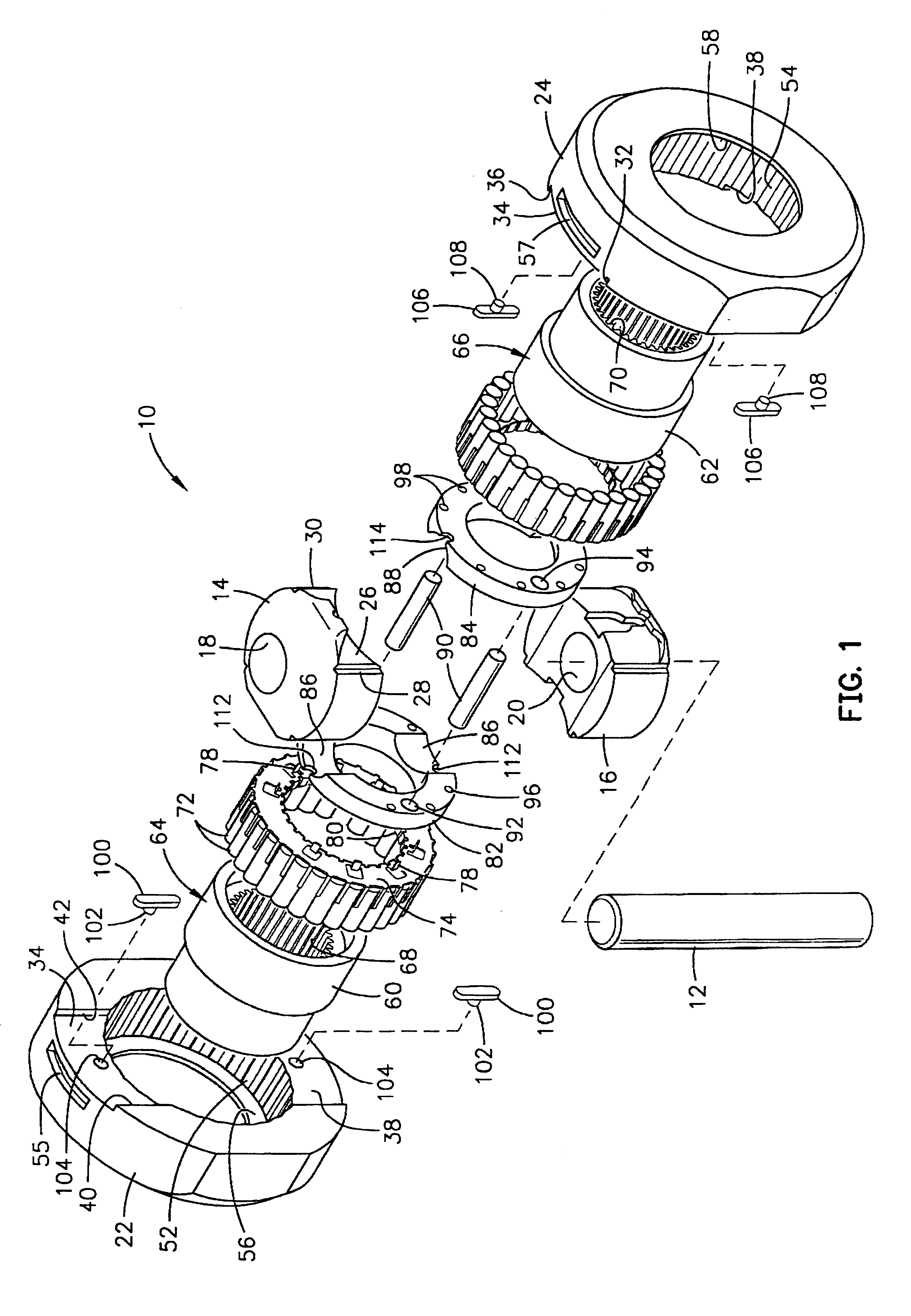
FIG. 1 is a perspective exploded view of an exemplary preferred embodiment of a differential in accordance with the invention;

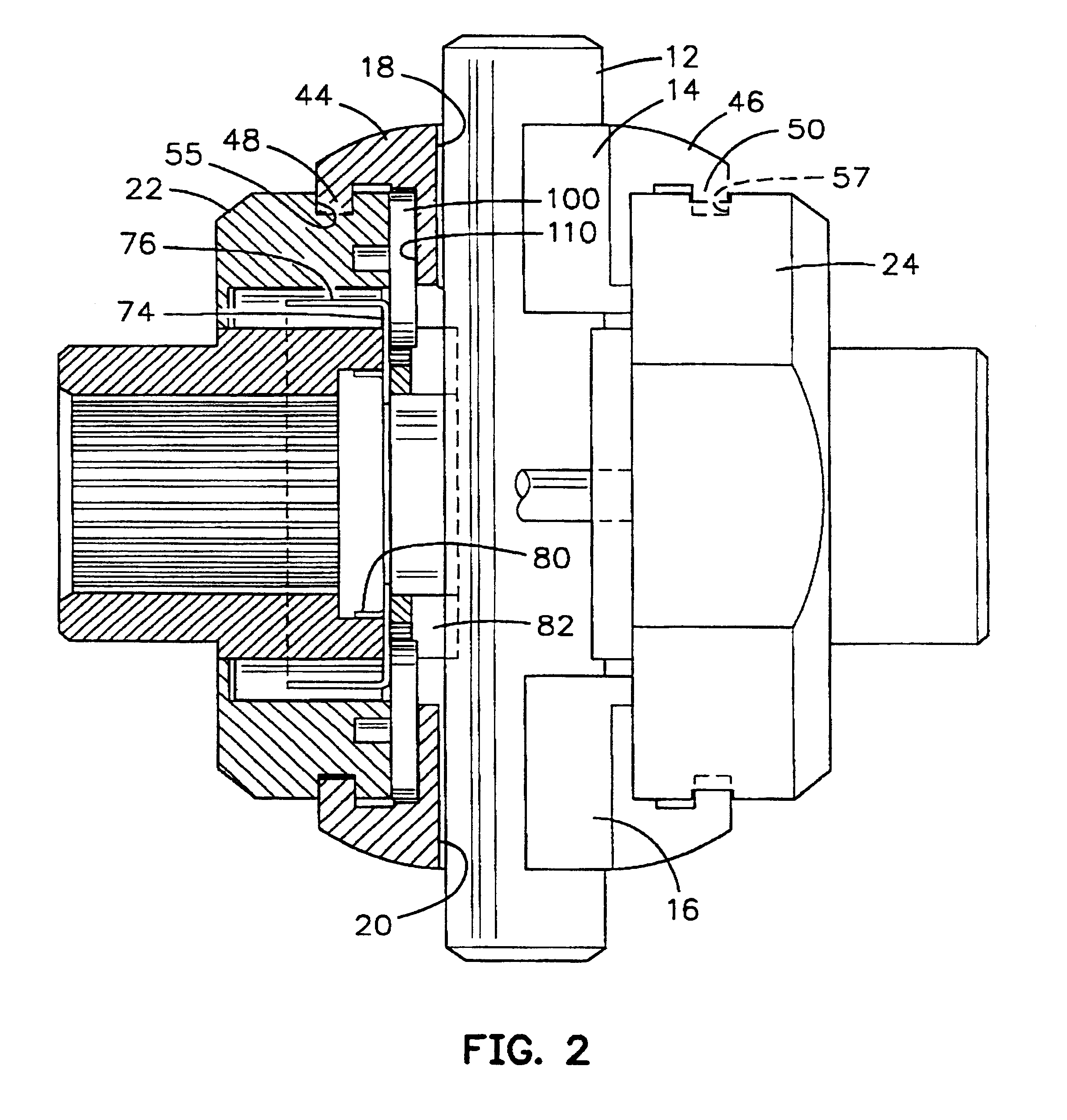
FIG. 2 is a front elevation view of the assembled differential partially in section;

FIG. 3 is a partial side elevation view of the assembled differential of FIG. 1 shown at rest; and

FIG. 4 is a view like FIG. 3 with the differential in driving condition.

Referring to the drawings, particularly to FIG. 1, an exemplary embodiment of a full-locking differential in accordance with the invention is illustrated in an exploded view and designated generally by the numeral 10. The illustrated differential is designed to be a full-locking differential and that replaces the standard automotive differential and which is user-installable into the existing differential case with no modificatio...


PUM


Abstract

A full-locking differential drive mechanism, comprised of an input drive which is composed of a pair of opposed spaced drive races, each having an inner diameter, a coupling block disposed between the races for coupling them to drive together, output driven means comprising a pair of co-axially disposed coupler members, each having an outer diameter disposed within the drive races inner diameters, which produces a bi-directional roller clutch disposed between the inner diameters and the outer diameters and operative to couple the drive races to the coupler members enabling driving engagement therebetween.

Description

The present invention relates to the field of differentials for vehicle drive trains and pertains particularly to positively locking differentials for motor vehicles.Land vehicles, such as automobiles, trucks, buses and the like, typically utilize what has become known as an open differential for the final drive system. An automotive differential is a mechanical assembly, often a system of gears, which is located in the driving axle of a vehicle. It applies power to the wheels while at the same time allowing a difference in their rotational speeds; this difference occurs when the vehicle turns because the outside wheel rotates faster than the inside wheel due to its larger turning radius. Differentials accomplish this function in various ways, depending on their particular designs.Differentials go back to the beginnings of the automotive era, but many of them had major traction problems in difficult terrain. Differentials have evolved into two broad classes: (1) Standard, or "open" ...

Claims


Application Information

Patent Timeline
Patent Type & Authority Patents(United States)
IPC IPC(8): F16D41/066F16D41/00
CPCF16D41/064Y10T74/19005F16H48/12
Inventor ZENTMYER, JOHN
Owner ZENTMYER JOHN
Learn More