Acceleration sensor for detecting inertia forces

a technology of acceleration sensor and inertia force, which is applied in the direction of acceleration measurement, measurement devices, instruments, etc., can solve the problems of inability to interrogate the measuring section, inability to reliably determine the low deceleration value, and sensor is not capable of separating dynamic positional change from static positional change of phase boundary

Inactive Publication Date: 2001-08-21
REIME GERD
View PDF15 Cites 17 Cited by
  • Summary
  • Abstract
  • Description
  • Claims
  • Application Information

AI Technical Summary

Problems solved by technology

However, low deceleration values cannot be determined reliably with this.
In this way it is not possible to interrogate the measuring sections in each case, so that this sensor is not in a position to make static changes differentiable from dynamic changes.
The difference values detectable thereby are not free of environmental influences, such as, e.g., an aging of the sensor or evaporation of liquid, but in particular the sensor is not capable of differentiating dynamic positional changes from static positional changes of the phase boundary.

Method used


Image

  • Acceleration sensor for detecting inertia forces
  • Acceleration sensor for detecting inertia forces
  • Acceleration sensor for detecting inertia forces

Examples


Embodiment Construction

The invention is explained further below by means of specific embodiments shown in the drawings. It is self-evident that these specific embodiments are not to be considered as an exhaustive enumeration and that the physical concept is not to be limited to the principle shown in the drawings.

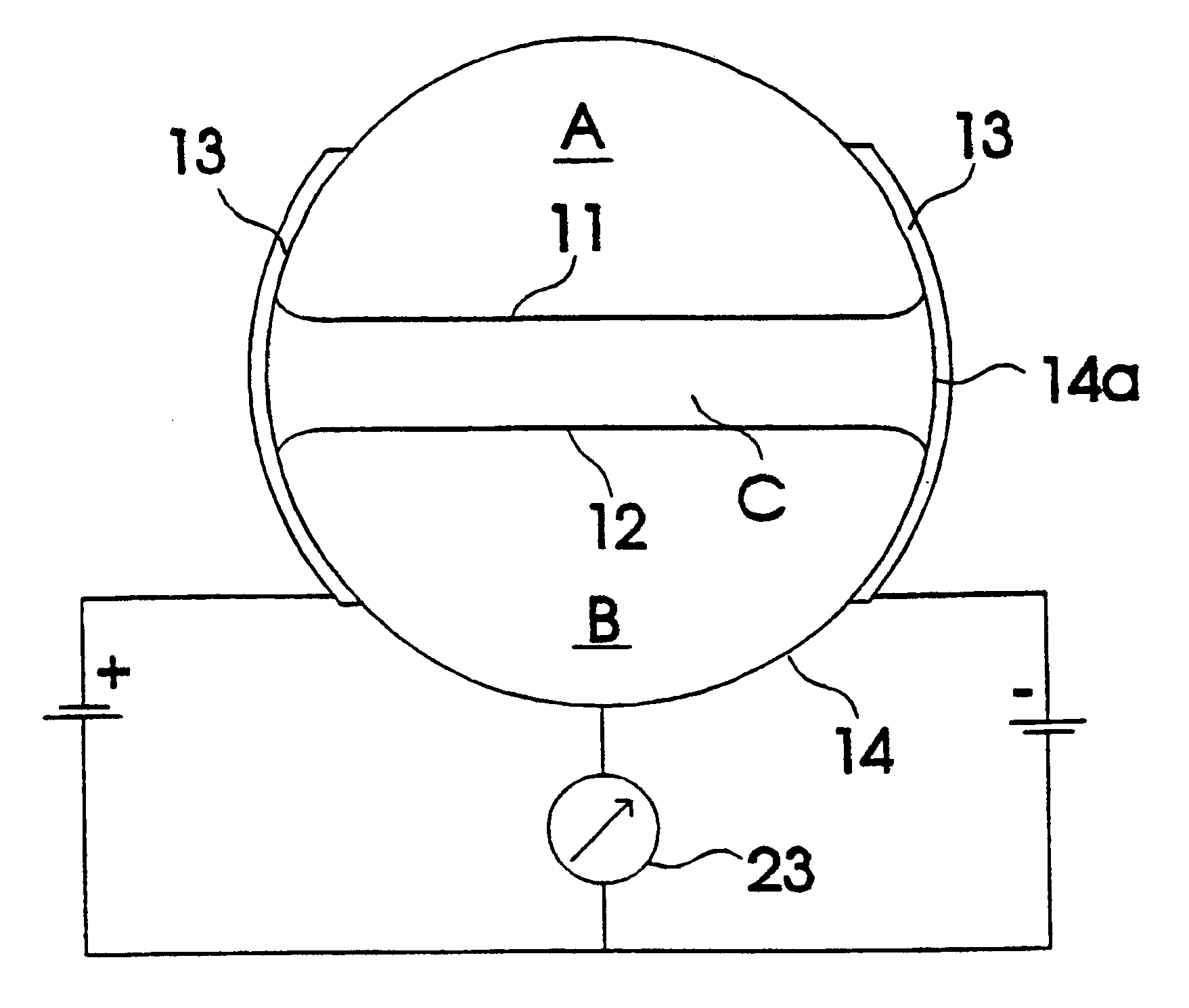
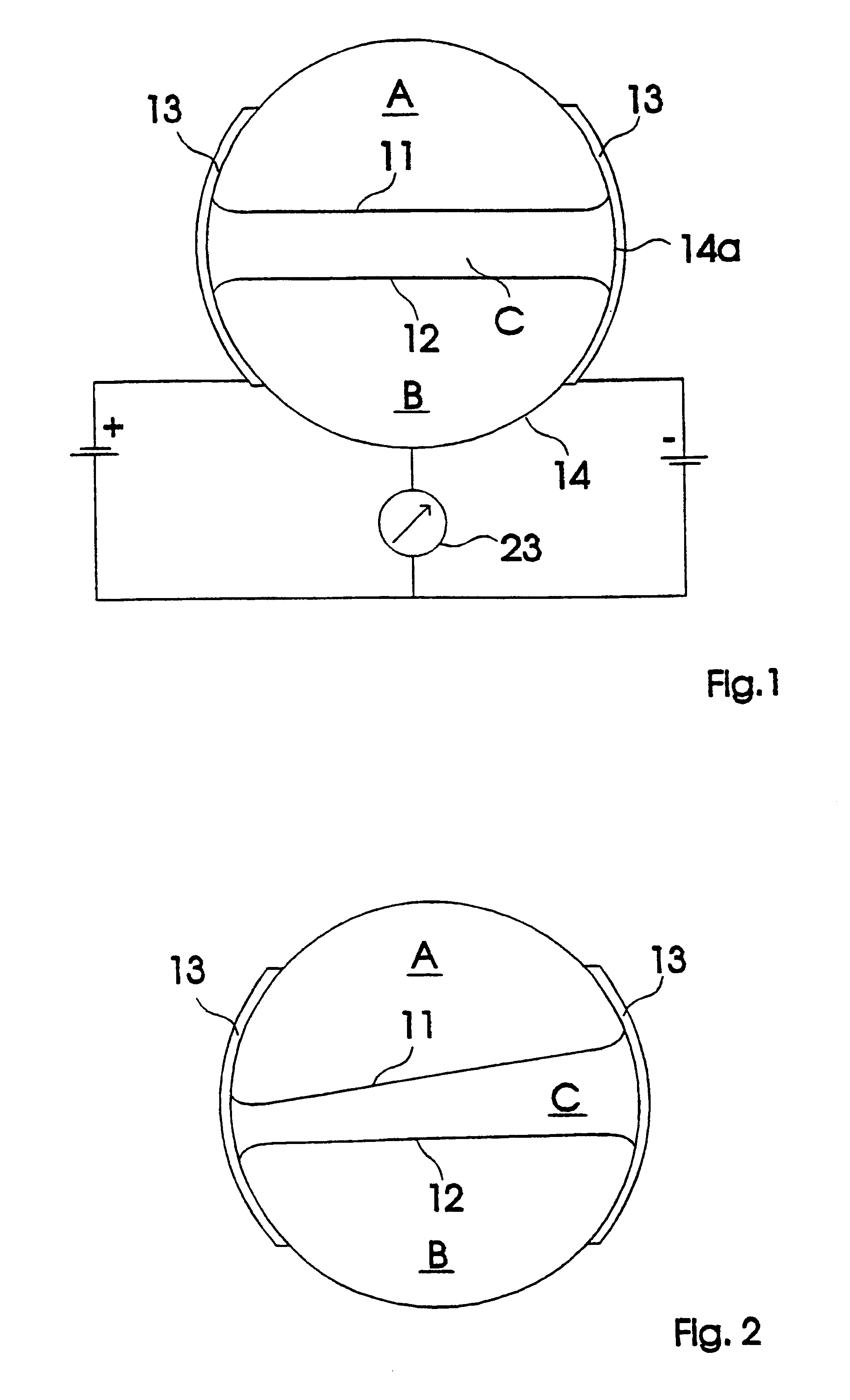
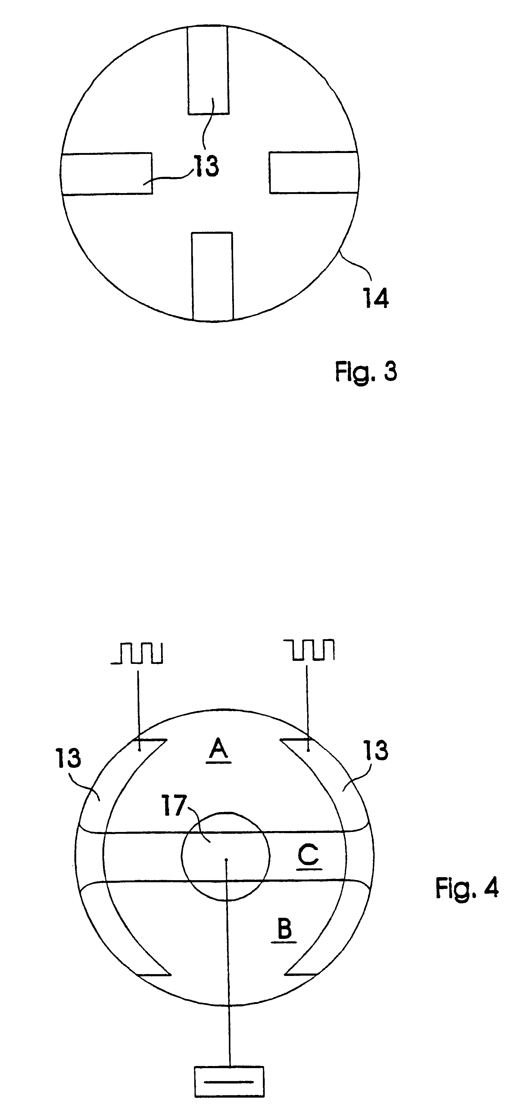
An accelerometer 10 (FIG. 8) for detecting inertial forces is shown in the figures.

In the first specific embodiments of FIGS. 1-7, several media form at least two phase boundaries, which also behave dynamically differently in the case of the appearance of acceleration because of the different physical properties of the media. In the second specific embodiment of FIG. 9, it is possible to operate with only one phase boundary between two media A, B, since here the dynamic influences are leveled after their detection by the detection means 13 by means of a time constant Z. Thus, in all specific embodiments, there are differentiation means acting time-dependently, once in the form of the different me...


PUM


Abstract

The invention relates to an acceleration sensor for detecting inertia forces, in which several separable and non-miscible media are stored in a receptacle and from at least one interphase between the media. Differentiation agents are provided to distinguish dynamic changes of position of the interphase from static changes of position, and evaluation agents evaluate the dynamic changes of position for the gradual determination of acceleration. An acceleration sensor that reacts sensitively to acceleration and deceleration, but which emits no signal when the sensor is rotated away from zero-position is thus created.

Description

REFERENCE TO RELATED APPLICATIONThe present application stresses the priority of German Patent Application 197 02 392.4 of Jan. 24, 1997 and the German Utility Patent 297 09 688.5 of Jun. 3, 1997, the disclosure content of which also is a subject of the present invention.AREA OF THE INVENTIONThe invention concerns an accelerometer for detecting inertial forces. Essentially, changes independent of time are understood as static position changes and essentially, time-dependent changes are understood as dynamic position changes.PRIOR ARTAn accelerometer of this kind is known from GB 2 022 822 A with a phase boundary between a liquid and air in a vessel. In this case, light is beamed through the phase boundary, detection means detecting the varying reflective index as a result of a motion of the sensor and this the phase boundary. Differential means are provided which make it possible to differentiate a time-dependent change of the phase boundary based on a vibration from a change depend...

Claims


Application Information

Patent Timeline
Patent Type & Authority Patents(United States)
IPC IPC(8): G01P15/12G01P15/093G01P15/18G01P15/125G01P15/08G01P15/00
CPCG01P15/006G01P15/08G01P15/18G01P15/12G01P15/125G01P15/093
Inventor REIME, GERD
Owner REIME GERD
Why Eureka
Try Eureka