Muzzle brake

a technology of muzzle and sling, which is applied in the field of muzzle brake, can solve the problems of high overpressure level, detrimental to comfort and well-being, and arrangements which have not been very successful, and achieve the effects of reducing the pressure and reducing the sling weigh

Inactive Publication Date: 2001-08-21
DANEL
View PDF7 Cites 53 Cited by
  • Summary
  • Abstract
  • Description
  • Claims
  • Application Information

AI Technical Summary

Benefits of technology

Further according to the invention the springs may be pretentioned by inserting one or more spacer elements between the end of a spring and an annular step formation provided in the bore of the first element.

Problems solved by technology

Furthermore, they often also give rise to very high overpressure levels which may be detrimental to the comfort and well being of the crew operating the gun.
Although it has been known in the past to employ muzzle brakes with movable components, the arrangements which have hitherto been suggested have not been very successful, usually because of mechanical failure.

Method used


Image

  • Muzzle brake
  • Muzzle brake
  • Muzzle brake

Examples


Embodiment Construction

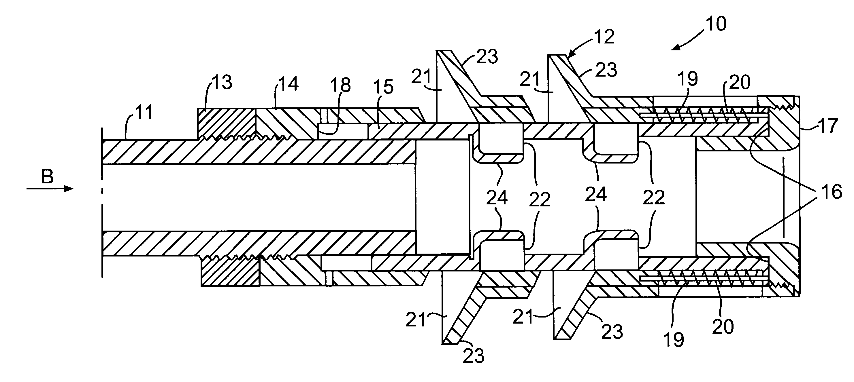
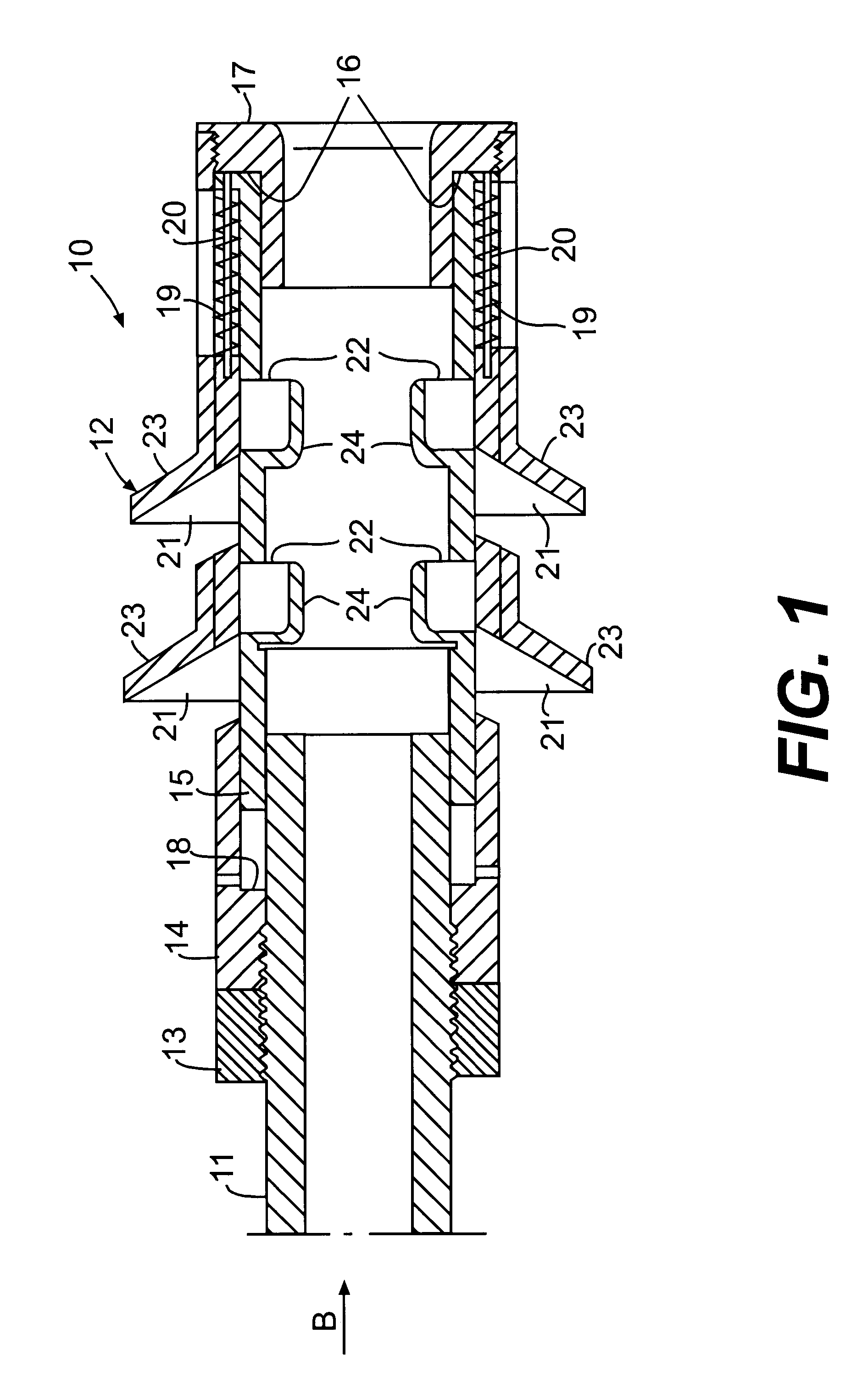
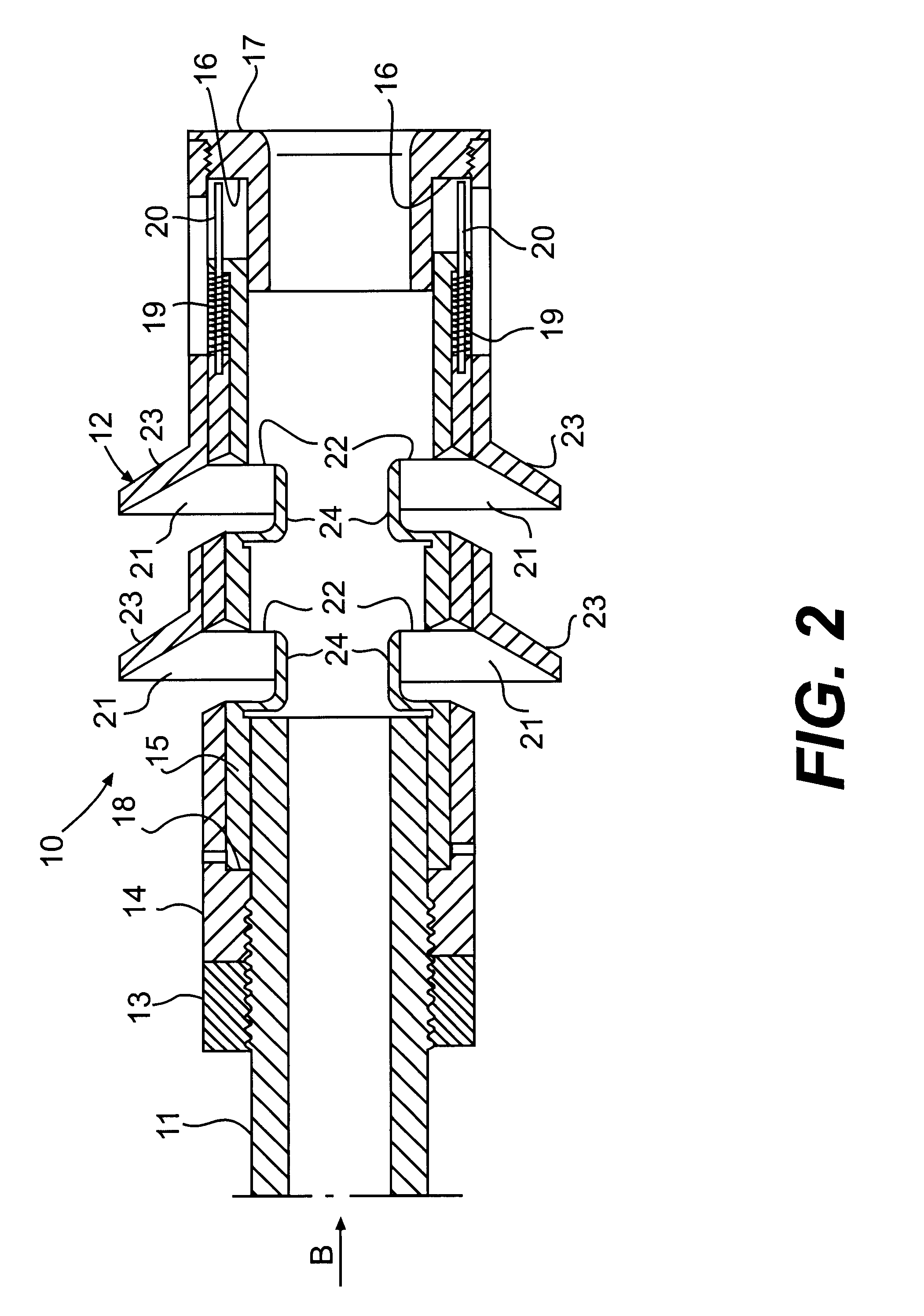
One embodiment of the invention will now be described by way of example with reference to the enclosed drawings.

In this embodiment of the invention a muzzle brake 10 is shown as fitted to the barrel 11 of a gun such as an artillery piece of the like (not shown). Brake 10 comprises an annular steel member 12 which is screwed onto the firing end of barrel 11, and secured thereto by means of a lock nut 13.

Member 12 comprises an outer annular element or sleeve 14, in the bore of which an inner annular element or sleeve 15 is telescopically movable between a first extreme position, defined by an annular shoulder formation 16 provided by the underside of the rim of an annular end cap 17 which fits into the mouth of the bore of sleeve 14 so that cap 17 is located stationary relative to barrel 11, and a second extreme position defined by another annular shoulder formation 18 provided in the bore of sleeve 14 in a position spaced from said shoulder formation 16.

The free end of sleeve 15 furt...


PUM


Abstract

A muzzle brake for a gun which comprises an annular member mountable on the firing end of the muzzle of the gun, which member comprises a pair of concentrically located annular elements of which the first one is mounted stationary relative to the muzzle of the gun and the second one is slidably movable against the biasing action of a spring relative to said first element in a direction opposite the firing direction of the gun, said movement taking place under the influence of the exhaust gas resulting from the firing of a projectile by the gun, and said movement being from a first extreme position into which said spring forces said second element, in which position the brake is in the "off' position, to a second extreme position where the brake is in the fully "on' position, in which position said exhaust gas can force the first element, and hence the muzzle of the gun, to move in the firing direction, and so counteract the recoil action of the gun.

Description

BACKGROUND AND PRIOR ARTThis invention relates to a muzzle brake for reducing the recoil action resulting from the firing of a gun.Muzzle brakes which serve to reduce the recoil action of a gun when it is fired, operate on the principle that they utilise the forward momentum of the pressure wave produced by the expanding exhaust gas which follows the projectile on firing of the gun, by deflecting some of such exhaust gas in a suitable manner to produce a forward impulse on the brake and hence the barrel of the gun, in this way at least balancing to some degree the recoil impulse on the barrel of the gun.Most muzzle brakes are characterised by the fact that they comprise static components such as baffle plates and apertures so that the braking action effected by them is rather abrupt and hence capable of interfering with the smooth recoil action and balance of the gun. Furthermore, they often also give rise to very high overpressure levels which may be detrimental to the comfort and ...

Claims


Application Information

Patent Timeline
Patent Type & Authority Patents(United States)
IPC IPC(8): F41A21/36F41A21/00
CPCF41A21/36
Inventor DOWNING, DIRK JOHANNESNIEWOUDT, TIELMAN
Owner DANEL
Why Eureka
Try Eureka