Grouting method for rigidly connecting two elements using a binder, and in particular for anchoring one element in another

a technology of rigid connection and grouting, which is applied in the direction of lamination apparatus, medical science, prosthesis, etc., can solve the problems of inability to achieve perfect binder distribution, inability to join the two parts, and inability to achieve good grouting, so as to facilitate the positioning of the part to be sealed in the recess, falling, and avoid the effect of slipping

Inactive Publication Date: 2001-08-28
PROSEAL
View PDF20 Cites 36 Cited by
  • Summary
  • Abstract
  • Description
  • Claims
  • Application Information

AI Technical Summary

Benefits of technology

This is true, in particular, in the medical field of prostheses, since it is at times necessary to remove a prosthesis, for instance in case of an infection, and this implies not only extracting the prosthesis but also eliminating all of the binder which holds it and which may contain infectious germs. Now, this curettage operation is a very delicate one, entailing the risk that the tools used may cut into the bone caput. It is therefore necessary to take many precautions and to carry out careful and lengthy work, which is a great strain on the patient.
The present invention makes it possible to overcome these drawbacks by proposing a method of grouting and sealing which permits perfect positioning of the part to be sealed and perfect distribution of the binder in just the right amount, and which furthermore makes it possible, if nec

Problems solved by technology

Both of these methods have drawbacks.
The first, in fact, does not make it possible to obtain perfect distribution of the binder so that air pockets, which are harmful to the good joining of the two parts, may be present.
The second does not permit perfect positioning of the part to be sealed as there may be substantial differences in the thickness of the layer of binder and, furthermore, it entails the risk of stratification of the binder when the part to be sealed is pushed in.
Furthermore, it is not easy to introduce into the recess that amount of binder which is precisely necessary to fill the empty space, wit

Method used


Image

  • Grouting method for rigidly connecting two elements using a binder, and in particular for anchoring one element in another
  • Grouting method for rigidly connecting two elements using a binder, and in particular for anchoring one element in another
  • Grouting method for rigidly connecting two elements using a binder, and in particular for anchoring one element in another

Examples


Embodiment Construction

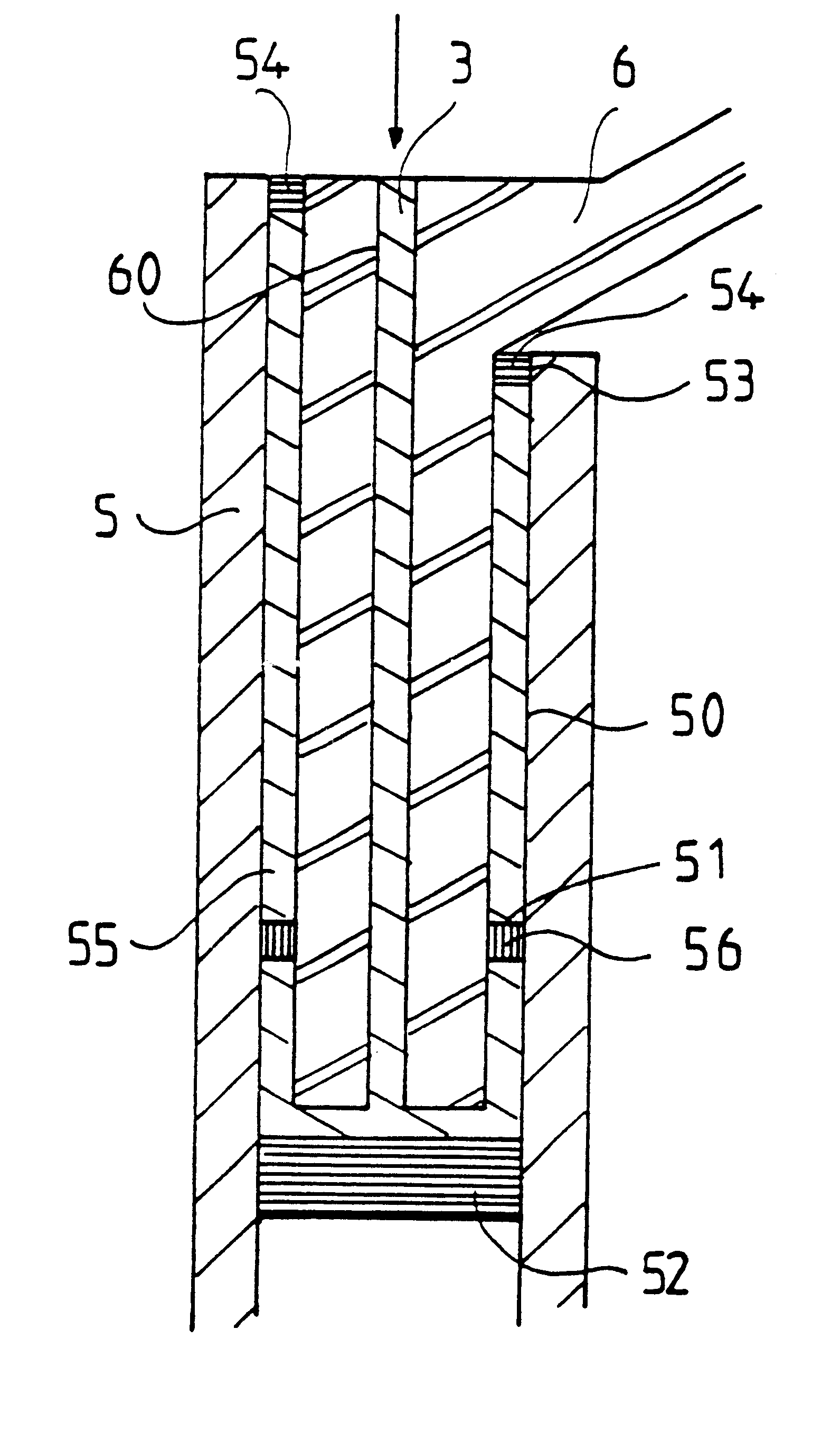
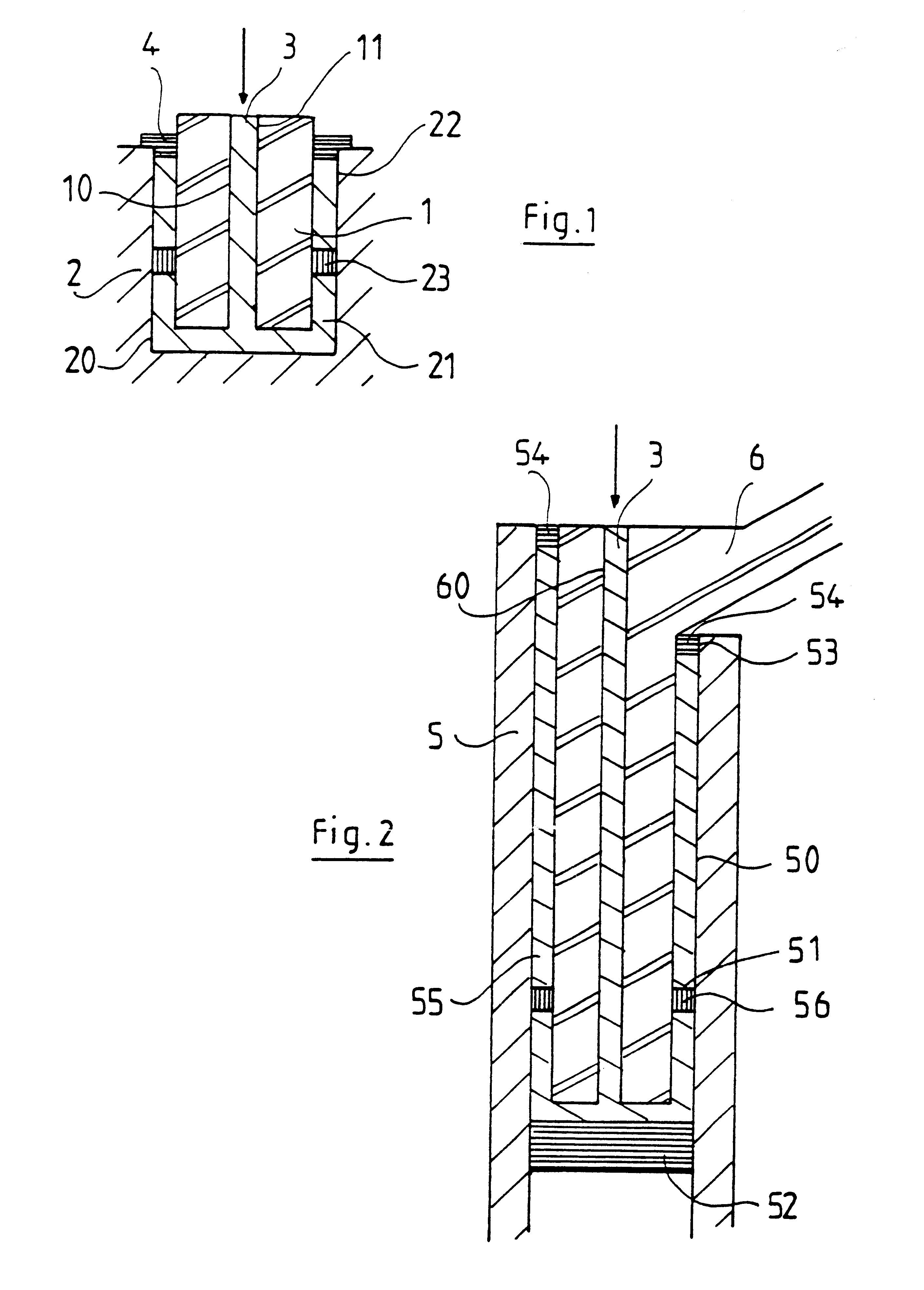
Referring to FIG. 1, there can be noted a part 1 sealed in a part 2 by means of the method of the invention. The part 1 has a channel 10, drilled axially in the direction of introduction of the part 1 into the recess 20 in the part 2. The part 1 is held by spacers 23 in the position which it is to occupy once sealed, whereupon the binder 3 is injected into the channel 10 from its outer opening 11, it spreading out in the channel 10 and then into the space 21 present between the part 1 and the wall of the recess 20, until reaching the edge 22 of the recess.

The edge 22 of the recess 20 can be provided with a packing part 4, which may have the shape of a collar, surrounding the part 1 and covering the space 21 so as to permit a better finish and create a certain tightness between the recess 20 and the part 1, so that upon the injection of the binder 3 resistance to the pressure is created, resulting in a better distribution of the binder 3.

In this way, particularly in the field of cons...


PUM

PropertyMeasurementUnit
Fractionaaaaaaaaaa
Fractionaaaaaaaaaa

Abstract

A method of grouting which permits the joining together of two parts by means of a binder and, more particularly, the sealing of one part in another, in particular the sealing of a prosthesis in a bone cavity. The method includes producing in the part to be sealed a channel which passes through the part along an axis substantially parallel to the axis of the introduction of the part to be sealed into the recess formed in the part intended to receive it, and injecting the binder into the channel until the binder fills the space between the part and the wall of the recess. Centering elements can be placed around the part in the space present between the part and the wall of the recess, and a packing part can be positioned, around the part to be sealed, on the opening of the recess. The injection channel made in the part which is to be sealed can be provided with a thread which makes it possible to introduce a threaded rod into it for the extraction of the part.

Description

1. Field of the InventionThe object of the present invention is a method of grouting which makes it possible to join together two parts by means of a binder the consistency of which permits either a rigid or a flexible fastening and, more particularly, the sealing of one part in another, whether in the field of masonry, carpentry, industry or medicine, such as bone and dental surgery, for the sealing of a prosthesis.2. Description of the Related Prior ArtTwo methods are currently employed when it is desired to seal one part in another part, which has a recess adapted to receive the first part by means of a binder which makes it possible to effect the joining together of the parts: One consists in introducing the part to be sealed into the recess in the other part and filling the empty space by distributing the binder therein, while the other consists in filling the recess with binder and then introducing the part to be sealed before the binder has hardened.Both of these methods have...

Claims


Application Information

Patent Timeline
IPC IPC(8): A61F2/30A61F2/46
CPCA61B17/8802A61F2/30724A61F2002/4631A61F2/30723
Inventor LEGRAND, JEAN-JACQUES
Owner PROSEAL
Why Eureka
Try Eureka