Method and apparatus for receiving spread spectrum signal

a technology of spread spectrum and receiver, which is applied in the direction of multiplex communication, synchronisation arrangement, blood vessels, etc., can solve the problems of difficult detection of synch chip timing and long time to complete the averaging procedur

Inactive Publication Date: 2001-08-28
NEC CORP
View PDF10 Cites 17 Cited by
  • Summary
  • Abstract
  • Description
  • Claims
  • Application Information

AI Technical Summary

Problems solved by technology

Therefore, it is difficult to detect the synch chip timings due to the fading.
However, i

Method used


Image

  • Method and apparatus for receiving spread spectrum signal
  • Method and apparatus for receiving spread spectrum signal
  • Method and apparatus for receiving spread spectrum signal

Examples


Embodiment Construction

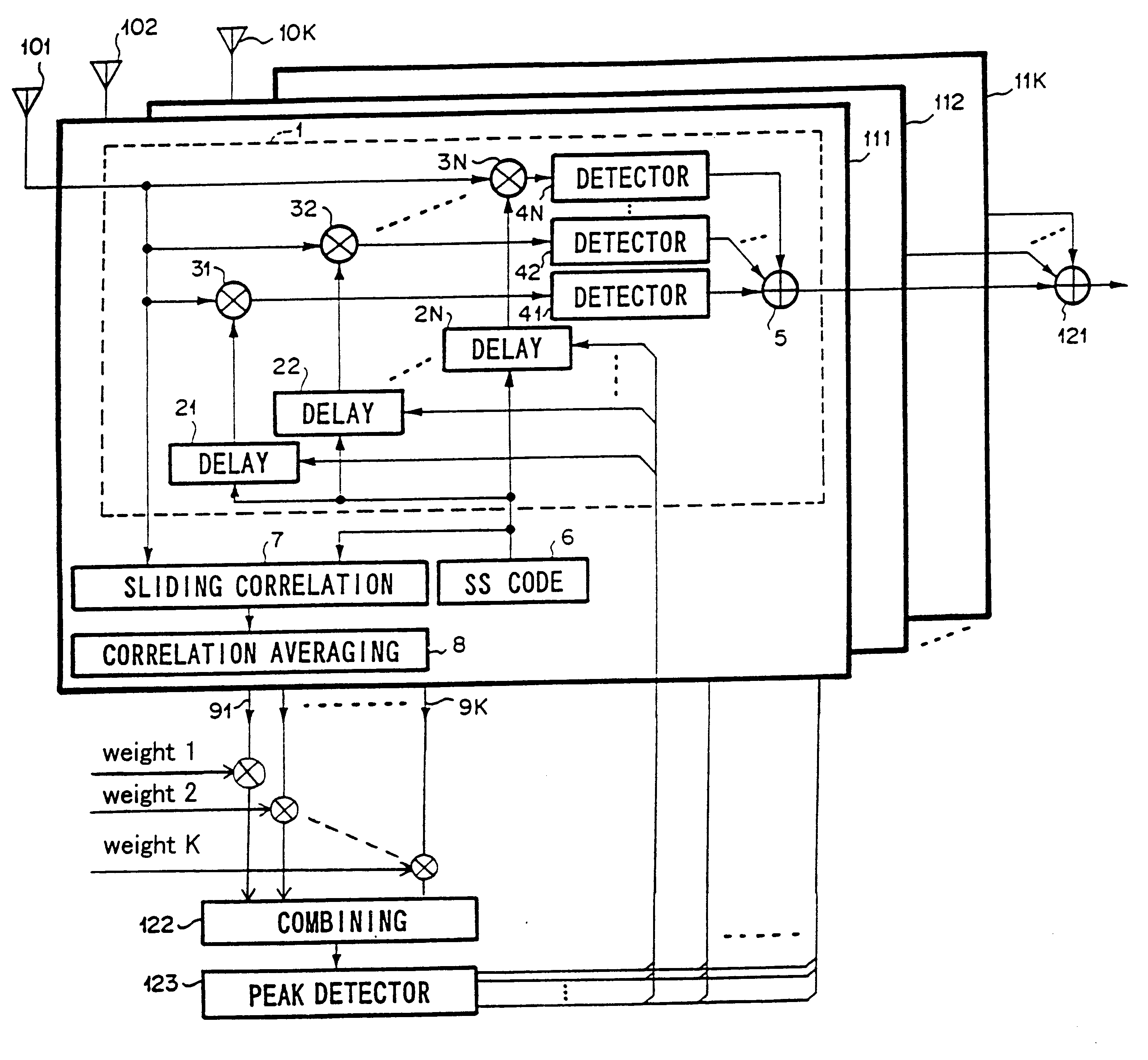
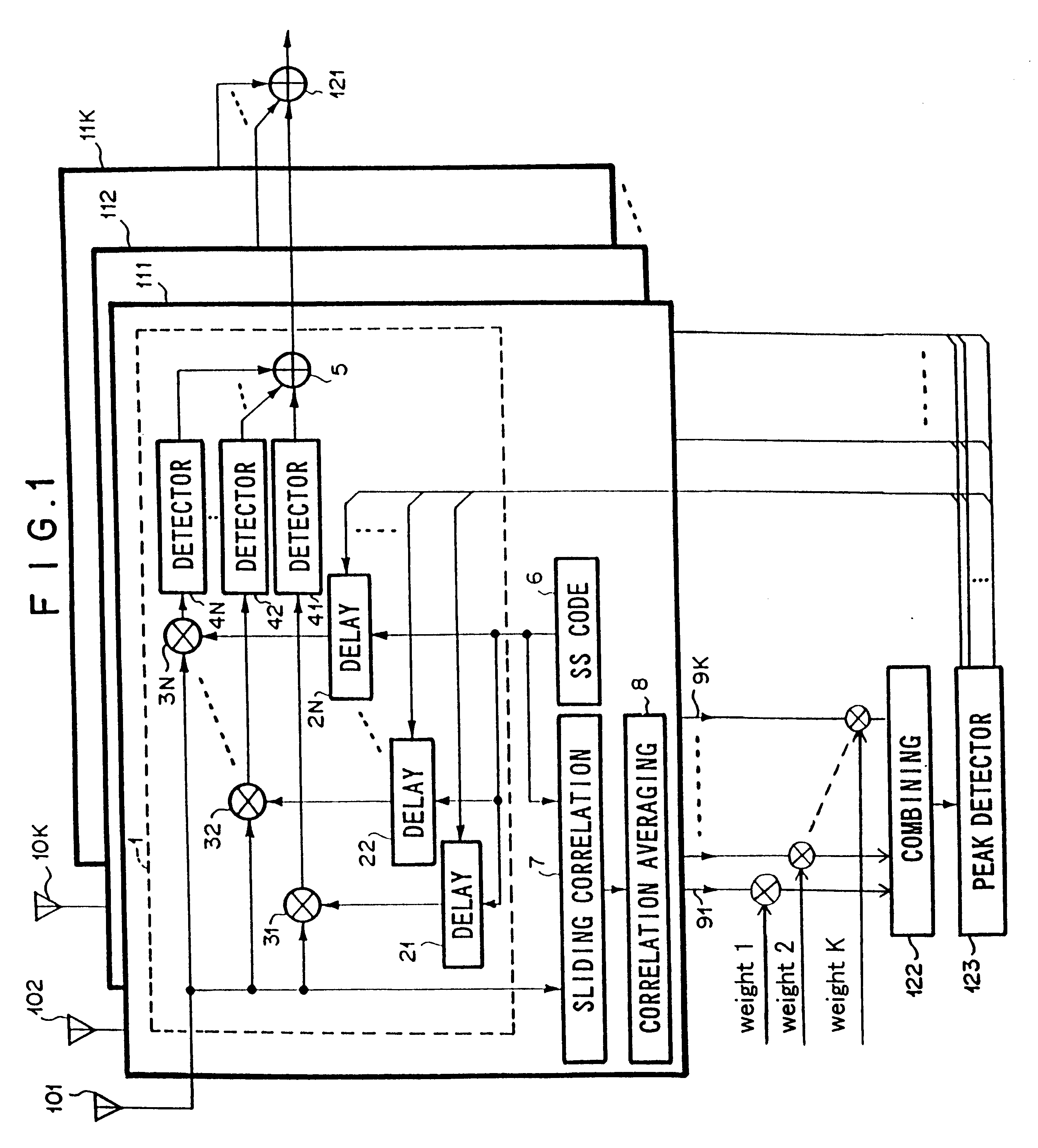
The mode of embodiment of the present invention is explained, referring to the drawings. The receiver of the present invention as shown in FIG. 1 is provided with delay profile combining means 122 for combining the delay profiles from a plurality of parallel receiving units 111 to 11K. On the basis of the output from delay profile combining means 122, synch chip timings of multipath signals are detected by peak detector means 123. Further, the detected timing is outputted commonly to receiving units 111 to 11K. Here, receiving units 111 to 11K are identical.

Receiving unit 111 comprises antenna 101, path combination receiving means 1, PN sequence generator 6, sliding correlation calculation means 7, and correlation averaging means 8.

Path combination receiving means 1 further comprises a plurality of delay circuits 21 to 2N, multipliers 31 to 3N, detector means 41 to 4N, and path combining means 5.

PN sequence generator 6 outputs a prescribed PN sequence with an arbitrary chip timing.

S...


PUM


Abstract

To synchronize spread spectrum (SS) signal with PN sequence, even when a Doppler frequency of fading is low. Delay profile combining means outputs a combined delay profile from delay profiles which are outputted from receiving units. Further, the synch chip timing which is obtained from the combined delay profile is fed commonly to receiving units for path diversity combining.

Description

BACKBROUND OF THE INVENTION1. Technical Field of the InventionThe present invention relates to a method and apparatus for receiving a spread spectrum (SS) signal which is to be synchronized with a Pseudo-Noise (PN) sequence for de-spreading.2. Description of the Prior ArtThe synch chip timing between the spread spectrum (SS) signal and the Pseudo-Noise (PN) sequence which is used for de-spreading is detected by independent antennas to combine the multipath signals from each antennas, as disclosed, for example, in JP 9-64845 A (1997).In a conventional SS signal receiver under a direct sequence (DS) system as shown in FIG. 5, independent receiving units 111 to 11K with antennas 101 to 10K are connected in parallel with antenna diversity combining unit 121. Here, receiving units 111 to 11K are identical.The signal received by antenna 101 and the spread spectrum (SS) sequence from PN sequence generator 6 are inputted into sliding correlation calculation means 7.The calculation of the sl...

Claims


Application Information

Patent Timeline
IPC IPC(8): H04B1/707H04B1/7115H04B7/08H04B7/26H04L7/00H04W16/28H04W56/00H04W88/02
CPCH04B1/707
Inventor AOYAMA, AKIO
Owner NEC CORP
Why Eureka
Try Eureka