Method and apparatus for controlling battery charging current

a charging current and battery technology, applied in the field of battery chargers, can solve the problems of limiting the dc power output of the ac adapter, and the inability to use a larger power to charge the rechargeable battery,

Inactive Publication Date: 2001-09-11
LENOVO PC INT
View PDF4 Cites 93 Cited by
  • Summary
  • Abstract
  • Description
  • Claims
  • Application Information

AI Technical Summary

Problems solved by technology

The DC power that is output by the AC adapter, therefore, is restricted.
Thus, even if a power source capable of supplying

Method used


Image

  • Method and apparatus for controlling battery charging current
  • Method and apparatus for controlling battery charging current
  • Method and apparatus for controlling battery charging current

Examples


first embodiment

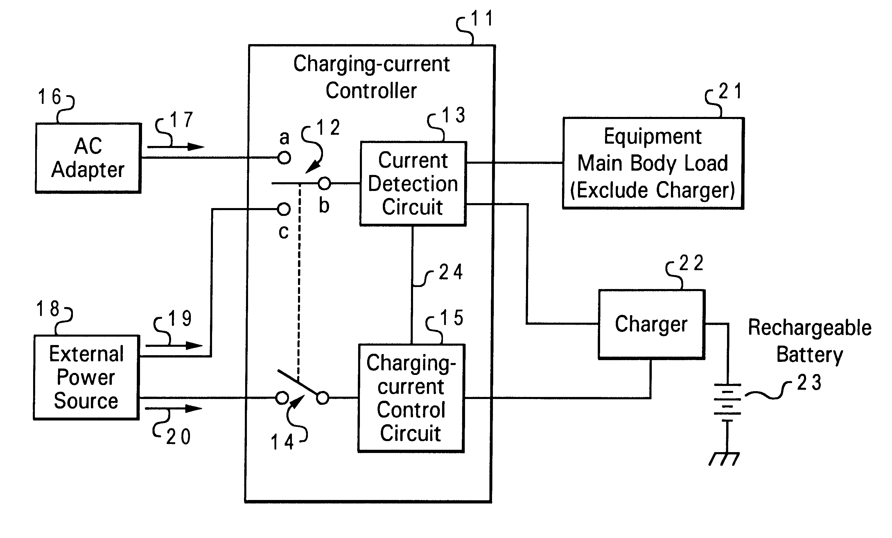
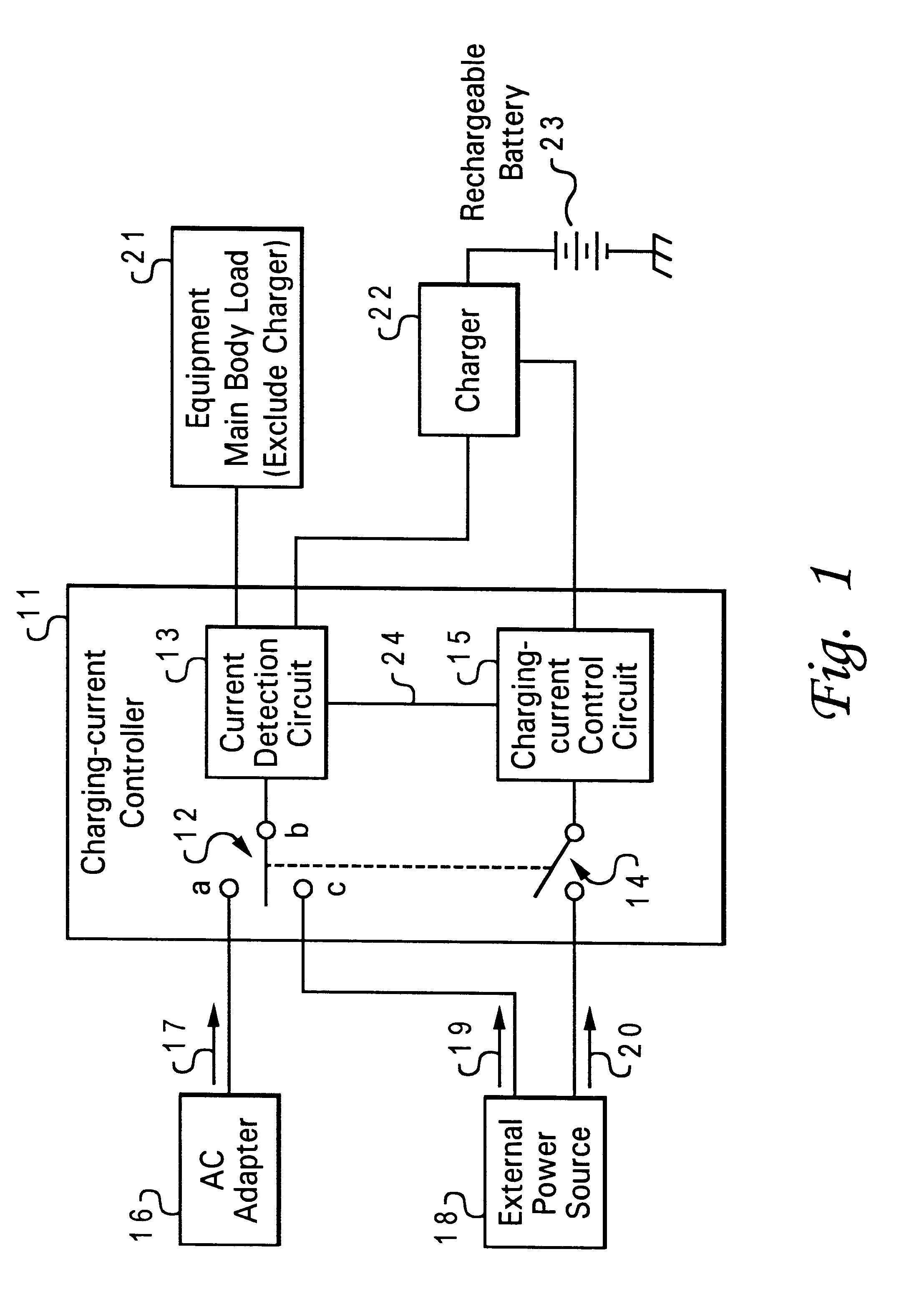
With reference now to the figures, and in particular to FIG. 1, a block diagram depicting a portable PC having a charging-current controller in accordance with a first embodiment of the present invention. A charging-current controller 11 according to the first embodiment comprises power path control switch 12, a current detection circuit 13, signal connection means 14, and a charging-current control circuit 15.

One end of the power path control switch 12 is connected to the current detection circuit 13, while the other end is selectively connected to either an AC adapter 16 or an external power source 18 that is incorporated in an expansion unit. The power path control switch 12 has three states a, b, and c. In the state a, the power path control switch means 12 selects the AC adapter 16. In the state c, the power path control switch 12 selects the external power source 18 incorporated in an expansion unit. In the state b, the power path control switch 12 selects neither the AC adapt...

second embodiment

Referring now to FIG. 3, a second embodiment of the present invention is depicted. A charging-current controller 41 according to the second embodiment comprises a power path control switch 12, a current detection circuit 13, a signal connection 14, and a charging-current control circuit 42. Since the power path control switch 12, the current detection circuit 13, and the signal connection 14 are the same as those of the first embodiment shown in FIG. 1, their function is as described above.

The function of the charging-current control circuit 42 is to control direct current (charging current), which flows in a charger 22, to an optimal value in accordance with a direct current value detected by the current detection circuit 13. This function is the same as the charging-current control circuit 15 of the first embodiment shown in FIG. 1. The difference between the charging-current control circuit 42 of the second embodiment and the charging-current control circuit 15 of the first embod...


PUM


Abstract

A method and apparatus for controlling battery charging current selectively receive electrical power from either a first external power source or a second external power source and outputs part of the power source to a charger for charging a battery. A reference value supplying apparatus gives a first reference value equivalent to the output current capability of the first external power source when a charging-current controller is connected to the first external power source and gives a second reference value equivalent to the current capability of the second external power source when the charging-current controller is connected to the second external power source. A current detection circuit detects current that the charging-current controller receives from either the first external power source or the second external power source and a charging current control circuit controls a charging current in the charger so that the charging current does not exceed the first or second reference value detected by the current detection circuit.

Description

1. Technical FieldThe present invention relates to battery chargers, and more particularly, to a charging-current controller for efficiently charging a rechargeable battery of a portable device where multiple external power sources are alternatively available.2. Description of the Related ArtWith the spread of mobile computing, portable personal computers (hereinafter referred to as portable PCs) of various sizes and functions have been developed. For example, there are notebook personal computers (PCs), sub-notebook PCs, palmtop PCs, PDAs (personal data assistants) or the like.Portable PC's typically incorporate a battery within their main housing. This battery makes it possible for a user to use a portable PC in an environment where a line power source is not readily available. Typically, a rechargeable battery is used so that it may be charged and used repeatedly.In an environment where a line power source can be utilized, the user connects an AC adapter (to which the line power ...

Claims


Application Information

Patent Timeline
IPC IPC(8): H02J7/00G06F1/28H02J7/10
CPCH02J7/0055H02J7/0068H02J7/00714H02J2207/40
Inventor ODAOHHARA, SHIGEFUMISUZUKI, KEIJI
Owner LENOVO PC INT
Why Eureka
Try Eureka