Quick release mechanism for motorcycle saddlebag

a saddlebag and quick release technology, applied in the field of saddlebags, can solve the problems of cumbersome access to the saddlebag, parts protruding into the saddlebag, and inconvenient and time-consuming removal of the saddlebag,

Inactive Publication Date: 2001-09-25
ARON MATHEW R
View PDF14 Cites 70 Cited by
  • Summary
  • Abstract
  • Description
  • Claims
  • Application Information

AI Technical Summary

Problems solved by technology

Removing a saddlebag may be inconvenient and time consuming because the saddlebag is often bolted to the mounting bracket, which in turn is bolted to the frame of the motorcycle.
A d...

Method used


Image

  • Quick release mechanism for motorcycle saddlebag
  • Quick release mechanism for motorcycle saddlebag
  • Quick release mechanism for motorcycle saddlebag

Examples


Embodiment Construction

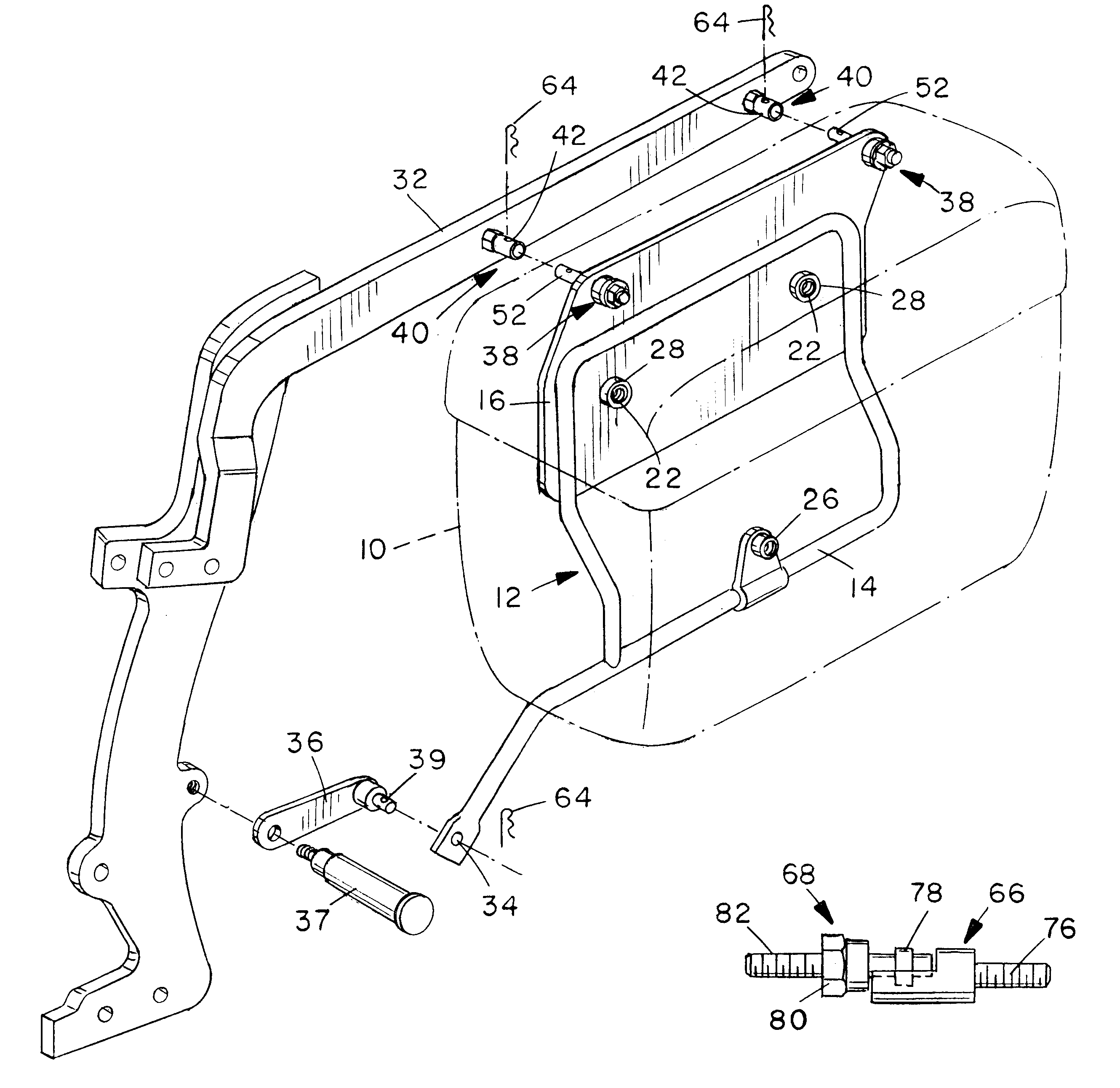
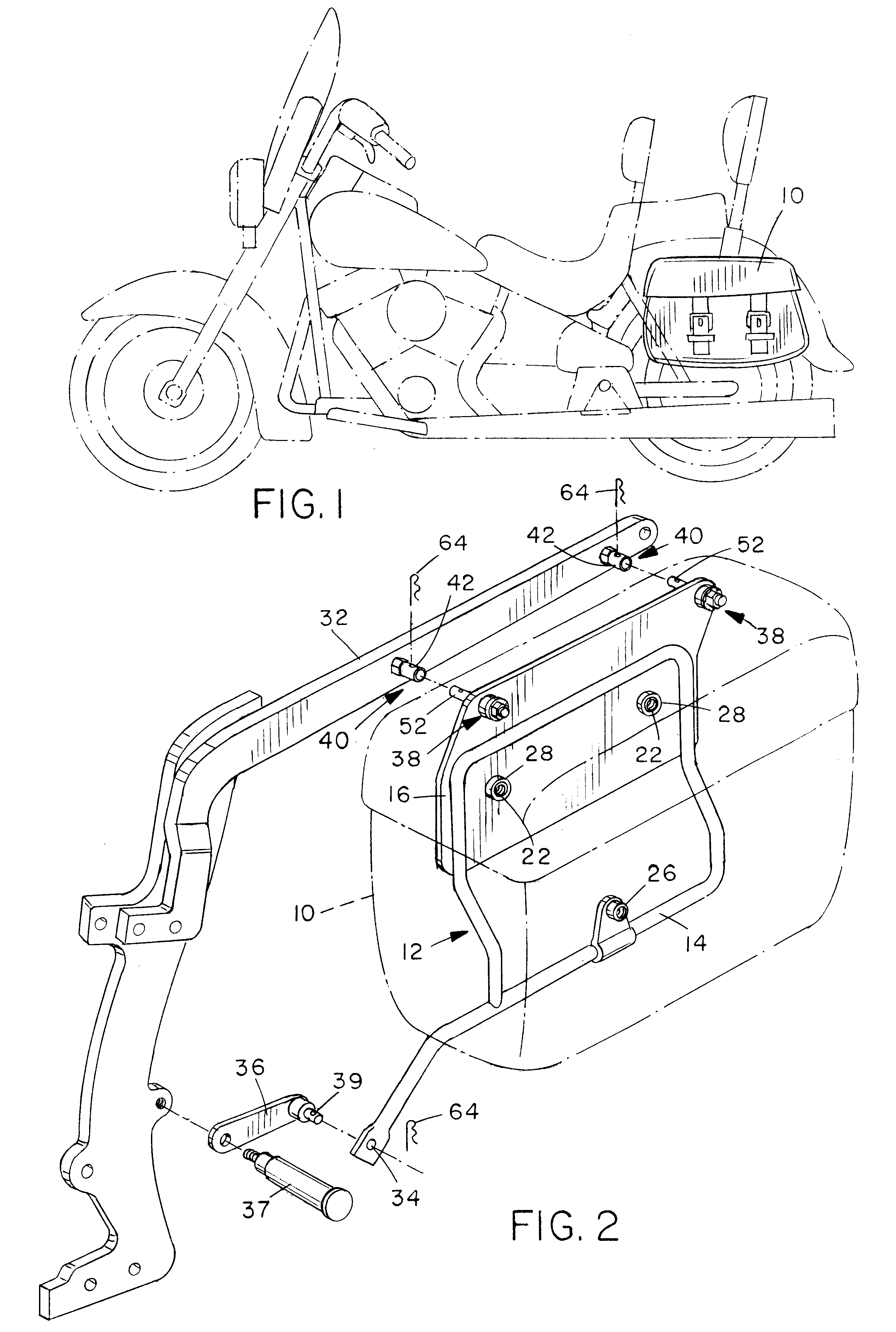
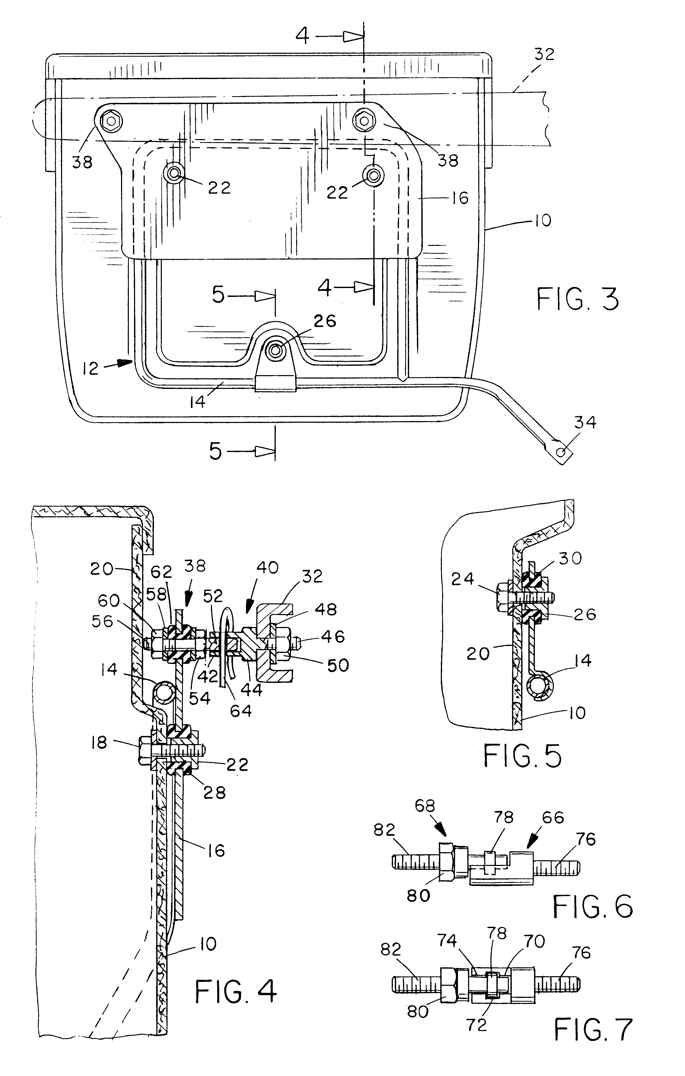
As illustrated in FIG. 1, a saddlebag assembly 10 is mounted on a motorcycle (shown in phantom line). As illustrated in FIG. 2, saddlebag assembly 10 includes a saddlebag (shown in phantom line) and a mounting bracket 12. A portion 14 of mounting bracket 12 is tubular and a portion 16 is plate-like. As illustrated in FIGS. 4 and 5, the saddlebag is attached to mounting bracket 12 by two bolts 18 that extend through holes in the inboard side of the saddlebag wall 20 and are received in two threaded studs 22 in plate-like portion 16 and by one bolt 24 that extends through another hole in the inboard side of saddlebag wall 20 and is received in the threaded stud 26 on tubular portion 14. Grommets 28 and 30 in these holes damp any vibration. Saddlebag assembly 10 is attached, more or less permanently, to a fender brace portion of the frame 32 of the motorcycle by two bolts (not shown) that extend through a pair of holes in plate-like portion 16 and frame 32 and by a third bolt (not show...


PUM


Abstract

A quick-release mounting system for a motorcycle saddlebag and a method for retrofitting a motorcycle with the system. The system includes two or more couplings with which one can retrofit a motorcycle by replacing each bolt of the original mounting system with one of the couplings. Each coupling includes a first coupling portion and a second coupling portion that can be removably coupled and uncoupled with one another in a quick-release manner.

Description

1. Field of the InventionThe present invention relates generally to saddlebags and, more specifically, to motorcycle saddlebags.2. Description of the Related ArtA motorcycle may have saddlebags for carrying the riders personal gear, repair tools or other items. One saddlebag is typically mounted to a bracket attached to the frame rearward of the rider's seat on each side of the motorcycle.Although many saddlebags are made of leather, others are made of fiberglass or a similar rigid material.Saddlebags generally must be removed to perform any significant maintenance on the motorcycle. Removing a saddlebag may be inconvenient and time consuming because the saddlebag is often bolted to the mounting bracket, which in turn is bolted to the frame of the motorcycle. For example, to remove each saddlebag from the HARLEY-DAVIDSON HERITAGE .RTM. motorcycle, one must unscrew four bolts to detach the saddlebag from the mounting bracket and unscrew three bolts to detach the mounting bracket from...

Claims


Application Information

Patent Timeline
IPC IPC(8): B62J9/00
CPCB62J9/001B62J9/23B62J9/26B62J9/27
Inventor ARON, MATHEW R.
Owner ARON MATHEW R
Why Eureka
Try Eureka