
Flow directed catheter

a catheter and flow direction technology, applied in the direction of catheters, coatings, etc., can solve the problems of difficult to advance the catheter from the proximal end without causing buckling, polyurethane is undesirable for the delivery of many beneficial agents, and the process of tracking a catheter to a target site with a guidewire becomes difficul

Inactive Publication Date: 2001-10-02
TYCO HEALTHCARE GRP LP
View PDF72 Cites 142 Cited by
  • Summary
  • Abstract
  • Description
  • Claims
  • Application Information

AI Technical Summary

Benefits of technology

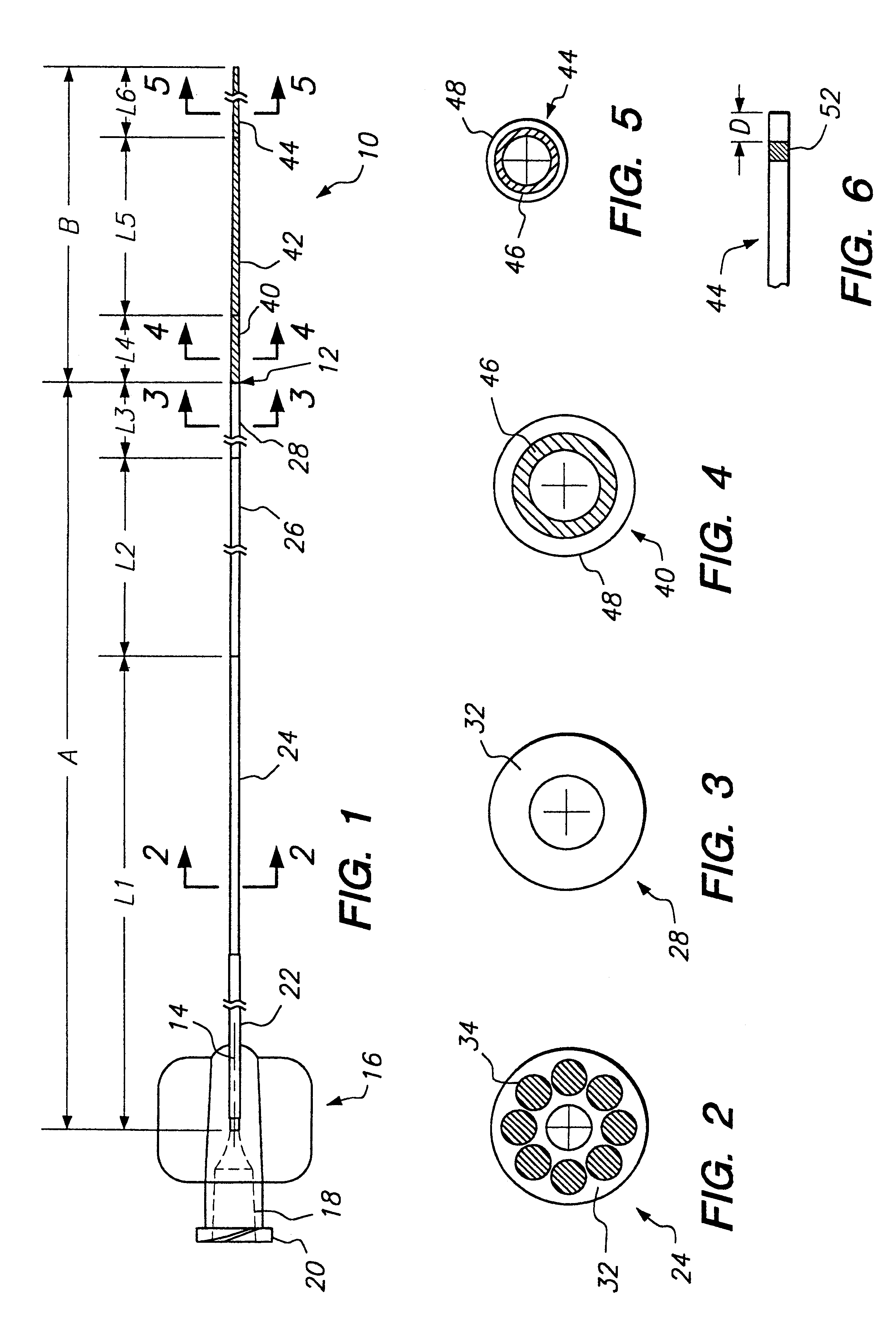
The present invention relates to a flow directed microcatheter having a changing flexibility and diameter between a proximal end and a distal end of the microcatheter. The changing properties of the microcatheter according to the present invention provide the flexibility of the distal tip needed to allow the microcatheter to be directed by the flow of blood within the vasculature and the columnar strength and torquability at the proximal end and along the length of the microcatheter needed to advance and direct the distal tip to the target site.
The present invention addresses this problem of kinking by forming the third section 28 of the proximal segment A and the first section 40 of the distal segment B with very similar properties of flexibility. In particular, the third section 28 of the proximal segment A and the first section 40 of the distal segment B are formed from materials having durometers which are substantially the same and having inner and outer dimensions which are substantially the same. For example, the outer diameters can vary by approximately 20 percent or less. The durometers of the proximal segment A and the distal segment B adjacent the joint 12 vary by less than about 40 percent, preferably less than 20 percent. This similarity in stiffness and size provides of the two segments at the joint 12 a very gradual transition at the fused joint 12 between the proximal and distal segment and inhibits kinking.

Problems solved by technology

The process of tracking a catheter to a target site with a guidewire becomes increasing difficult as the guidewire, catheter, and target vessel become very small, particularly, when the target site is deep within the vasculature and involves a highly tortuous path for access.
The extreme flexibility of the catheter distal tip results in difficulty in advancing the catheter from the proximal end without causing buckling.
However, polyurethane is undesirable for the delivery of many beneficial agents including solvents because many solvents will have the tendency to dissolve polyurethane by pulling plasticizers and loose radicals out of the polyurethane.
However, when delivery of the liquid embolic composition is attempted via conventional prior art polyurethane microcatheters, the catheter will swell and / or dissolve during use.
However, many materials which are compatible with various solvents including DMSO have insufficient flexibility and strength for use in the vary small diameter flow directed microcatheters.

Method used


Image

  • Flow directed catheter
  • Flow directed catheter

Examples


Embodiment Construction

One example of a microcatheter according to the present invention includes a proximal segment A formed of polyester elastomer wall material 32, such as Hytrel (available from New England Urethane and General Polymers), with polyester elastomer strands 34 having a higher durometer than the polyester elastomer of the walls. The polyester elastomer wall material 32 has a durometer of about 30 Shore D, while the strand material 34 has a durometer of about 82 Shore D. The proximal segment A preferably has a burst strength of approximately 160 psi or greater (11.25 kg / cm.sup.2) and is coextruded. A length L1 of the first section 24 may vary from about 100 cm to about 150 cm. The second transition section 26 in which the stiff strand material is gradually blended out has a length L2 of approximately 5 to 40 cm, preferably between 10 and 25 cm. The third section 28 which is formed entirely of the polyester elastomer material of the walls 32 without the strands 34 has a length L3 of approxim...


PUM

PropertyMeasurementUnit
lumen diameteraaaaaaaaaa

Abstract

A flow directed microcatheter is formed having a gradually changing flexibility and diameter between a proximal end and a distal end of the microcatheter. The changing properties of the microcatheter according to the present invention provide the flexibility of the distal tip needed to allow the microcatheter to be directed by the flow of blood within the vasculature, and the columnar strength and torquability at the proximal end and along the length of the microcatheter needed to advance and direct the distal tip to the target site. A proximal segment of the microcatheter includes a plurality of strands which vary in diameter to change the flexibility of the microcatheter. A distal segment of the microcatheter includes an inner layer which is compatible with solvents, such as DMSO, and an outer layer which provides strength and flexibility. The proximal segment and the distal segment of the microcatheter are joined by a kink resistant fuse joint.

Description

1. Field of the InventionThe invention relates to a catheter for delivery of beneficial agent s to a target site, and more particularly, the invention relates to a DMSO compatible, flow directed microcatheter for delivery of beneficial agents to a target site in the vasculature.2. Brief Description of the Related ArtMicrocatheters are used to deliver beneficial agents such as diagnostic, therapeutic, or occlusive agents to a target site within the vasculature. When a catheter is to be inserted into the various small blood vessels of the brain, heart, kidneys, etc., which are far away from the catheter insertion point and require passage of the catheter through many twists and turns of the vasculature, microcatheters are used which are able to access these various small blood vessels. Microcatheters may be either tracked with a guidewire to the target site or may be flow directed.A guidewire directed catheter is provided with a guidewire within the lumen of the catheter to assist in ...

Claims


Application Information

Patent Timeline
Patent Type & Authority Patents(United States)
IPC IPC(8): A61M25/00A61M25/01
CPCA61M25/0012A61M25/0045A61M25/0053A61M25/0054A61M25/0125A61M2025/0042
Inventor CHOW, SEAN L.
Owner TYCO HEALTHCARE GRP LP
Learn More