Methods and apparatus for inserting multi-lumen split-tip catheters into a blood vessel

a split-tip hemodialysis and catheter technology, which is applied in the direction of catheters, applications, guide wires, etc., can solve the problems of difficult insertion of additional difficulties of subcutaneous tunneling and placement of the flexible catheter, and difficulty in simply advancing the catheter over the guidewire, etc., to facilitate the entry of the catheter/stiffener assembly, facilitate the placement of the catheter, and facilitate the effect of dilating the blood vessel

Inactive Publication Date: 2012-06-26
BARD ACCESS SYST
View PDF631 Cites 36 Cited by
  • Summary
  • Abstract
  • Description
  • Claims
  • Application Information

AI Technical Summary

Benefits of technology

[0008]The intra-catheter stiffener elements are sufficiently stiffening to allow advancing the catheter over guidewires, but also sufficiently flexible to allow bending and looping of the catheter for proper placement within the vessel. Further, the intra-catheter stiffener elements prevent catheter kinking during the insertion process. In one embodiment, the intra-catheter stiffener elements have tapered distal ends which can facilitate entry of the catheter / stiffeners assembly into a blood vessel and / or assist in dilating the blood vessel.
[0009]One aspect of the invention provides methods and apparatus for inserting an antegrade tunneled, split-tip, hemodialysis catheter into a blood vessel. A distal portion of each of a plurality of guidewires is disposed in a blood vessel at a first location, generally in proximity to the vessel in which a portion of the catheter is to be placed. A subcutaneous tunnel is formed between the first location and a second location where a proximal end of the catheter can extend from the patient. An intra-catheter stiffener element is inserted into the proximal end of each catheter lumen until it extends beyond the distal end of that catheter lumen. The intra-catheter stiffener element can be releasably coupled, following insertion, to the proximal end of its respective catheter lumen via, for example, a mating luer assembly. Each guidewire can be inserted into to a distal end of a lumen in a respective intra-catheter stiffener element until that guidewire extends from the proximal end of that intra-catheter stiffener element. The catheter can then be advanced over the guidewires and into the blood vessel. Alternatively, the catheter can be advanced over the guidewires until a distal end of the catheter is adjacent to the vessel, at which point the catheter and guidewires can be advanced together into the vessel until the distal end of the catheter is at a desired location therein. Twisting the catheter while simultaneously advancing it along the guidewires can facilitate placement of the catheter into the vessel.
[0012]In a further related aspect, the methods provide for tunneling between the first and second location by using a pointed stylet. A distal end of a pointed stylet can be inserted through the skin at the second location and pushed toward the first location until the distal end extends therefrom. The distal end of the catheter is removably attached to a proximal end of the stylet. The stylet is then pulled from the first location until the distal end of the catheter extends therefrom, to facilitate an antegrade tunneled catheter.
[0013]Alternatively, a pointed distal end of a stylet can be inserted through the skin at the first location and pushed until it extends from the second location. The proximal end of the catheter can be removably attached to the proximal end of the stylet. The stylet is then pulled back toward the second location until the proximal end of the catheter extends therefrom. The catheter is then released from the stylet, thus positioning a retrograde tunneled catheter. To facilitate movement of the catheter within the tunnel, the proximal end of the catheter having mating lures or other coupling features can be removed or severed prior to attachment to the stylet. After tunneling the catheter, fluid couplings or other attachments can be disposed to the proximal end of the lumens.
[0017]The present invention is applicable in the field of hemodialysis, among others, for inserting a multi-tip catheter into a blood vessel. The methods and apparatus provide for insertion of a split-tip catheter without using a tearable sheath and avoid the problems associated with prior art approaches of split tip catheter insertion over a single guidewire.

Problems solved by technology

Unfortunately, the desired flexibility of these catheters presents insertion difficulties.
For example, simply advancing the catheter over a guidewire is very difficult since the catheter lacks sufficient stiffness to slide easily through the vessel wall and into the blood vessel to the desired location.
Flexible catheters present additional difficulties associated with subcutaneous tunneling and placement.
This approach is cumbersome, at best, and presents additional difficulties in maneuvering the instrument.
Further, this temporary rigid applicator approach, however, is poorly suited for placement of a catheter having a split at its distal end into two or more separate lumens (e.g., to further isolate a fluid extraction lumen from a return infusion lumen) because only one tip can be secured.

Method used


Image

  • Methods and apparatus for inserting multi-lumen split-tip catheters into a blood vessel
  • Methods and apparatus for inserting multi-lumen split-tip catheters into a blood vessel
  • Methods and apparatus for inserting multi-lumen split-tip catheters into a blood vessel

Examples


Embodiment Construction

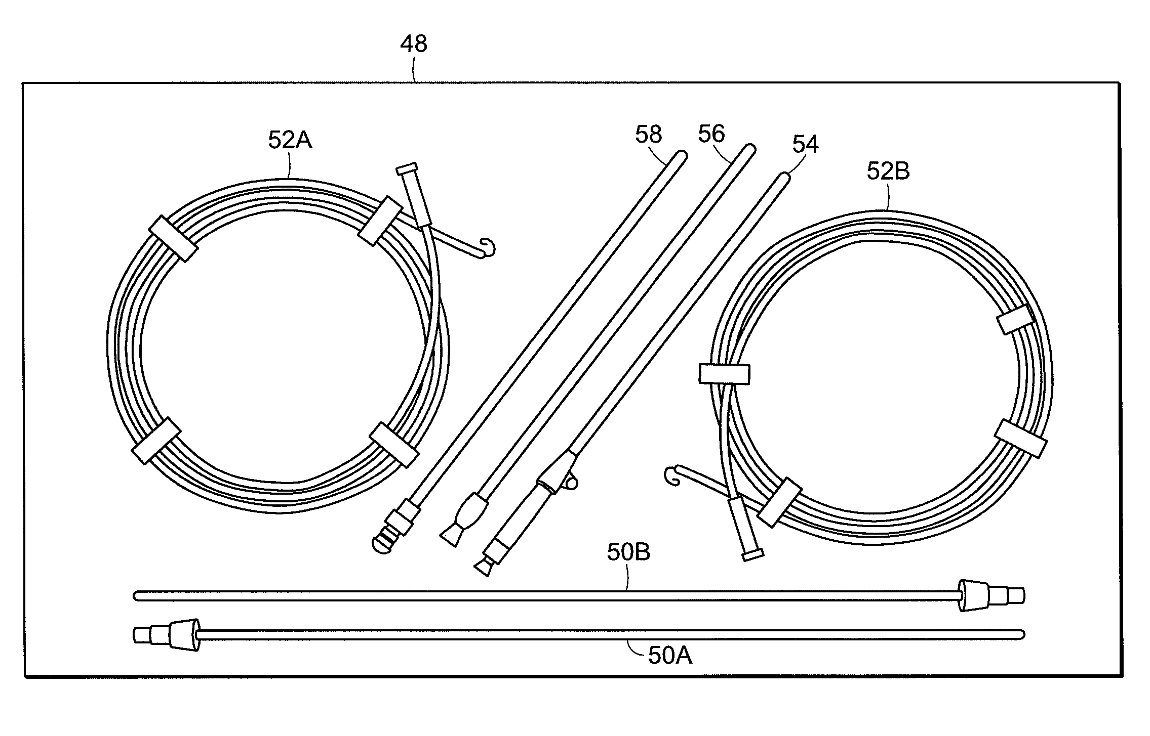
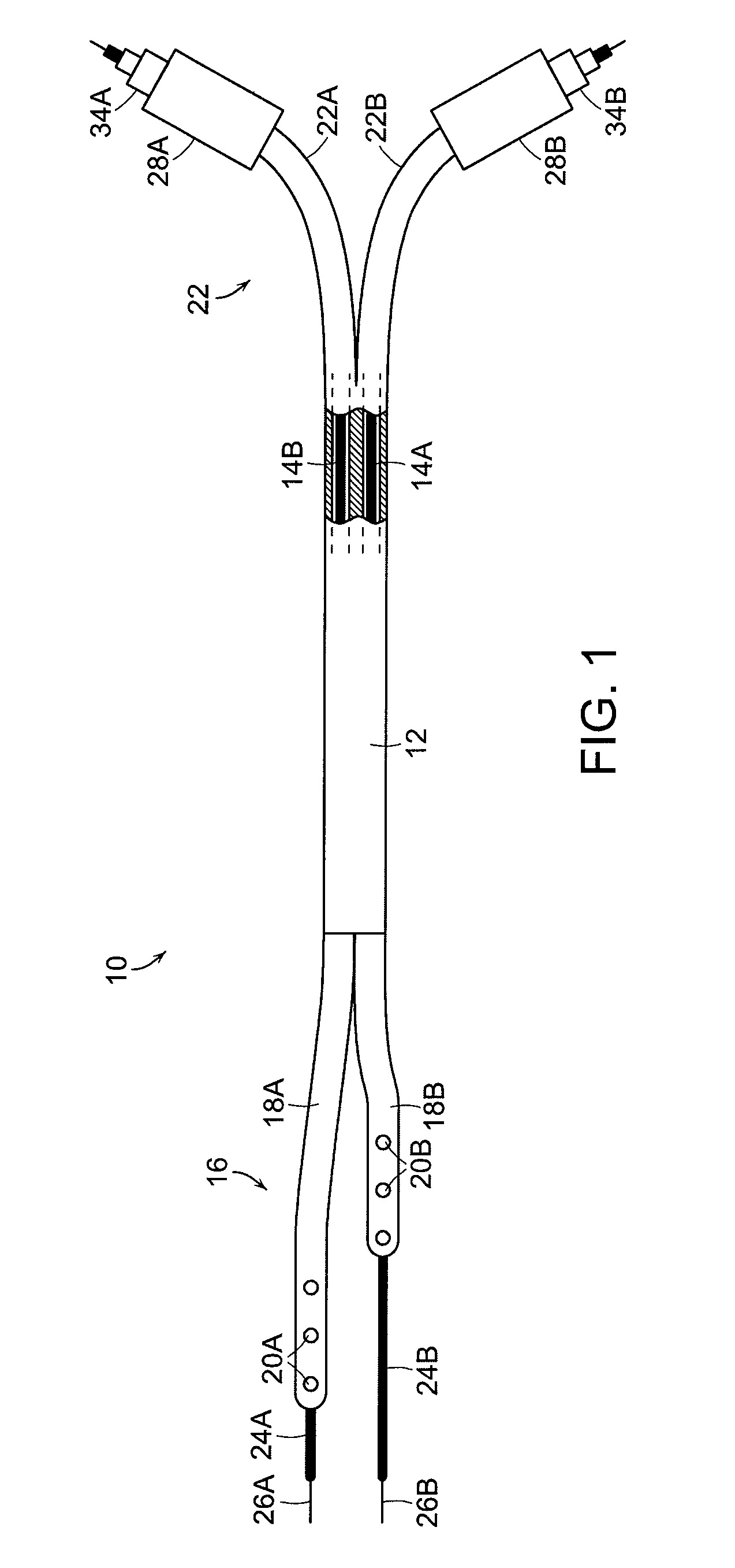
[0031]In FIG. 1 a catheter system 10 according to the invention is shown having a catheter body 12 with two internal lumens 14A and 14B. The catheter body 12 has a “split-tip” distal end 16 in which the body (and lumens) separate into two distal tip portions, 18A and 18B, which form a single-lumen distal blood removal extension tube and a single-lumen distal blood return extension tube, respectively. The split tips can, but need not have one or more side ports 20A and 20B, in fluid communication with one or the other of the lumens to facilitate blood removal and return, respectively, during hemodialysis. Alternatively, or in conjunction with side ports, the distal ends can be open to provide fluid passageways for blood removal and return. The proximal end 22 of the catheter body can also be split into separate segments 22A and 22B and terminates with two access ports 28A and 28B, which can include couplings 34 A and 34 B, such luer-locks or the like, to couple the catheter to a hemo...


PUM


Abstract

Methods and apparatus are disclosed for inserting flexible, multi-lumen catheters into blood vessels, and in particular, for inserting flexible, split-tip catheters into blood vessels. The invention accomplishes these objects by temporarily stiffening each catheter lumen and tip independently through use of intra-catheter stiffener elements disposed within the catheter lumens. This provides means for advancing the catheter / stiffeners assembly through a subcutaneous tunnel, and over a plurality of guidewires until a distal tip of the catheter is at a desired position within the vessel. The intra-catheter stiffener elements are sufficiently stiffening to allow advancing the catheter over guidewires, but sufficiently flexible to allow bending and looping of the catheter for proper placement within the vessel.

Description

CROSS REFERENCE TO RELATED APPLICATIONS[0001]The present application is a continuation of U.S. patent application Ser. No. 10 / 445,731, filed May 27, 2003 now abandoned, entitled “Methods And Apparatus For Inserting Multi-Lumen Split-Tip Catheters Into A Blood Vessel,” which is hereby incorporated by reference in its entirety.BACKGROUND OF THE INVENTION[0002]The invention relates to methods and apparatus for inserting a catheter into a body cavity and, more particularly, though not exclusively, to methods and apparatus for inserting a multi-lumen split-tip hemodialysis catheter into a blood vessel for hemodialysis.[0003]Multi-lumen catheters are desirable for various treatment applications such as hemodialysis where fluid extraction and infusion occur simultaneously. These multi-lumen catheters provide a single catheter application having multiple lumen channels each supporting independent flow, thus precluding the need for inserting multiple catheters or multiple-catheter assemblies...

Claims


Application Information

Patent Timeline
Patent Type & Authority Patents(United States)
IPC IPC(8): A61M25/00A61B5/00A61B17/34A61M25/01A61M31/00
CPCA61M25/0102A61M25/0194A61B17/3415A61M1/16A61M25/0026A61M25/09A61M29/00
Inventor NIMKAR, SHEKHAR D.ALBRECHT, STEPHEN E.ANAND, PARAMJITHTOBIN, ERIC
Owner BARD ACCESS SYST
Why Eureka
Try Eureka