Steerable Catheter With Flexing Tip Member

Active Publication Date: 2016-04-07
SANOVAS
View PDF16 Cites 33 Cited by
  • Summary
  • Abstract
  • Description
  • Claims
  • Application Information

AI Technical Summary

Benefits of technology

[0008]Accordingly, it is an objective of the invention to provide a simple to use, lightweight, low cost, highly accurate, steerable catheter

Problems solved by technology

Endoscopes and endoscopic systems are, currently, a reusable and expensive resource in a physician's armamentarium.
In addition, the endoscopic equipment systems required to operate endoscopes are often large, bulky and relatively immobile devices.
A limitation in the utility of the flexible endoscope is that their outer diameters are often too large, their inner ‘working channel’ diameters are often too small, and their lengths are often inadequate to appropriately diagnose and treat the anatomy and corresponding pathologies found in the far reaches of the body's organs, vessels and spaces.
A further limitation of the utility of the flexible endoscope is that the articulation of the distal tip, and thus, its maneuverability, is typically accomplished by complicated mechanical structures that control the manipulating of the flexible endoscope's distal tip.
As such, the maneuverabil

Method used


Image

  • Steerable Catheter With Flexing Tip Member
  • Steerable Catheter With Flexing Tip Member
  • Steerable Catheter With Flexing Tip Member

Examples


Embodiment Construction

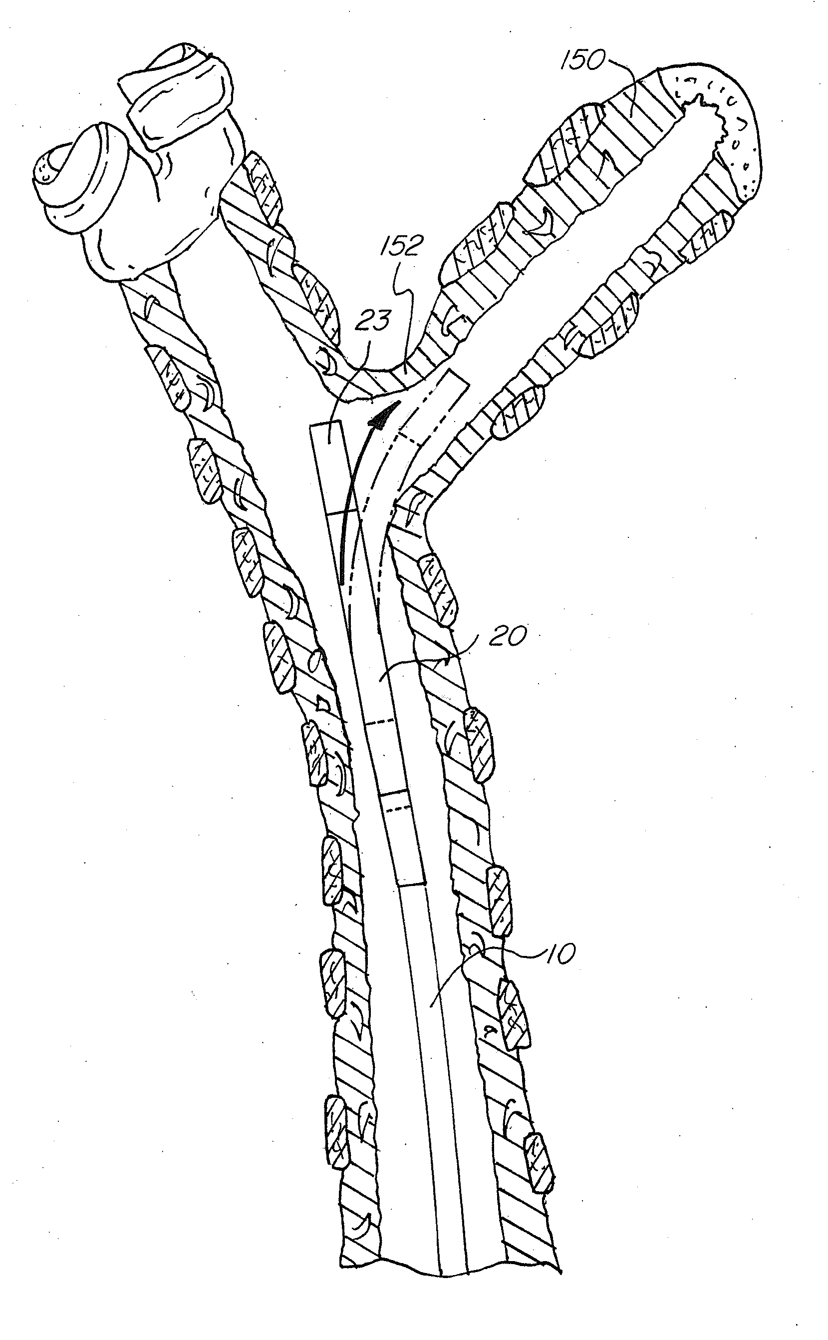
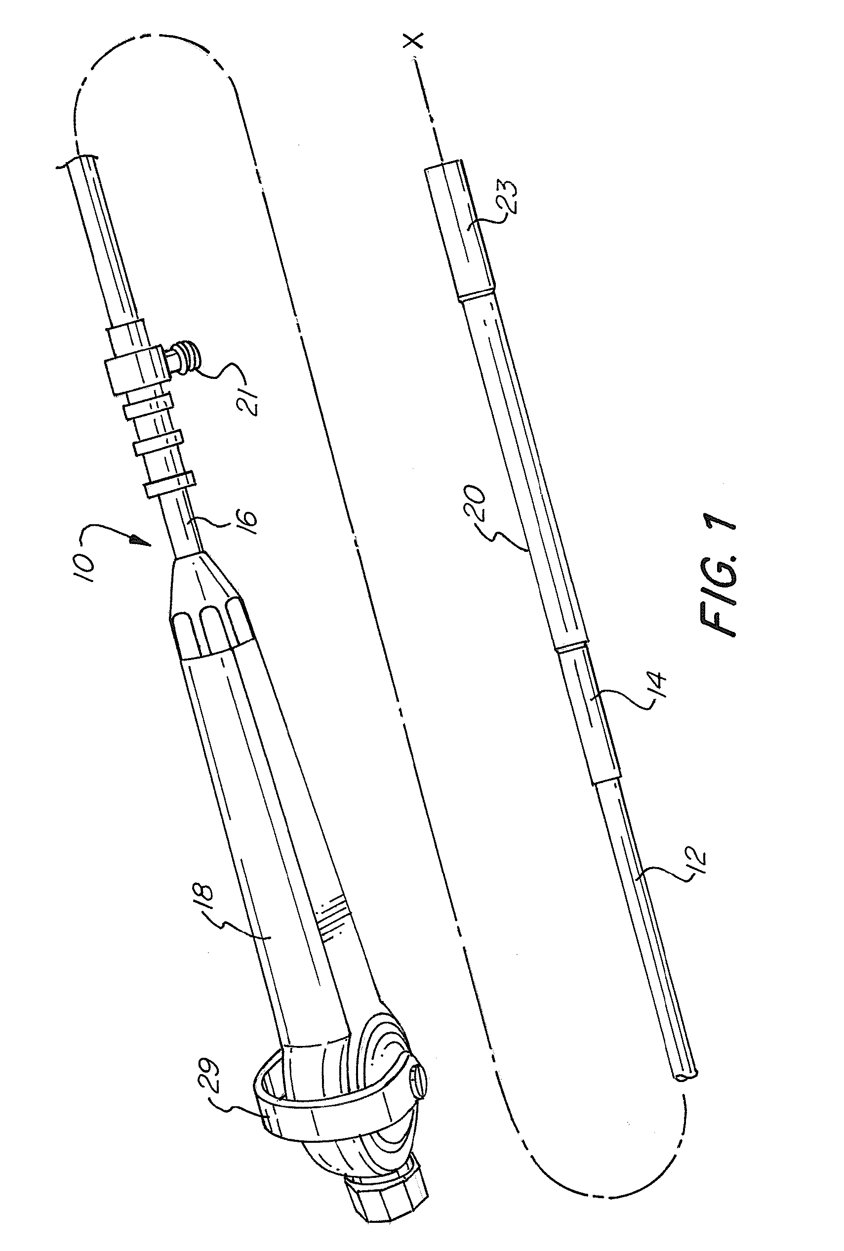
[0074]The basic components of one embodiment of a steerable catheter device in accordance with the invention are illustrated in FIG. 1. As used in the description, the terms “top,”“bottom,”“above,”“below,”“over,”“under,”“above,”“beneath,”“on top,”“underneath,”“up,”“down,”“upper,”“lower,”“front,”“rear,”“back,”“forward” and “backward” refer to the objects referenced when in the orientation illustrated in the drawings, which orientation is not necessary for achieving the objects of the invention.

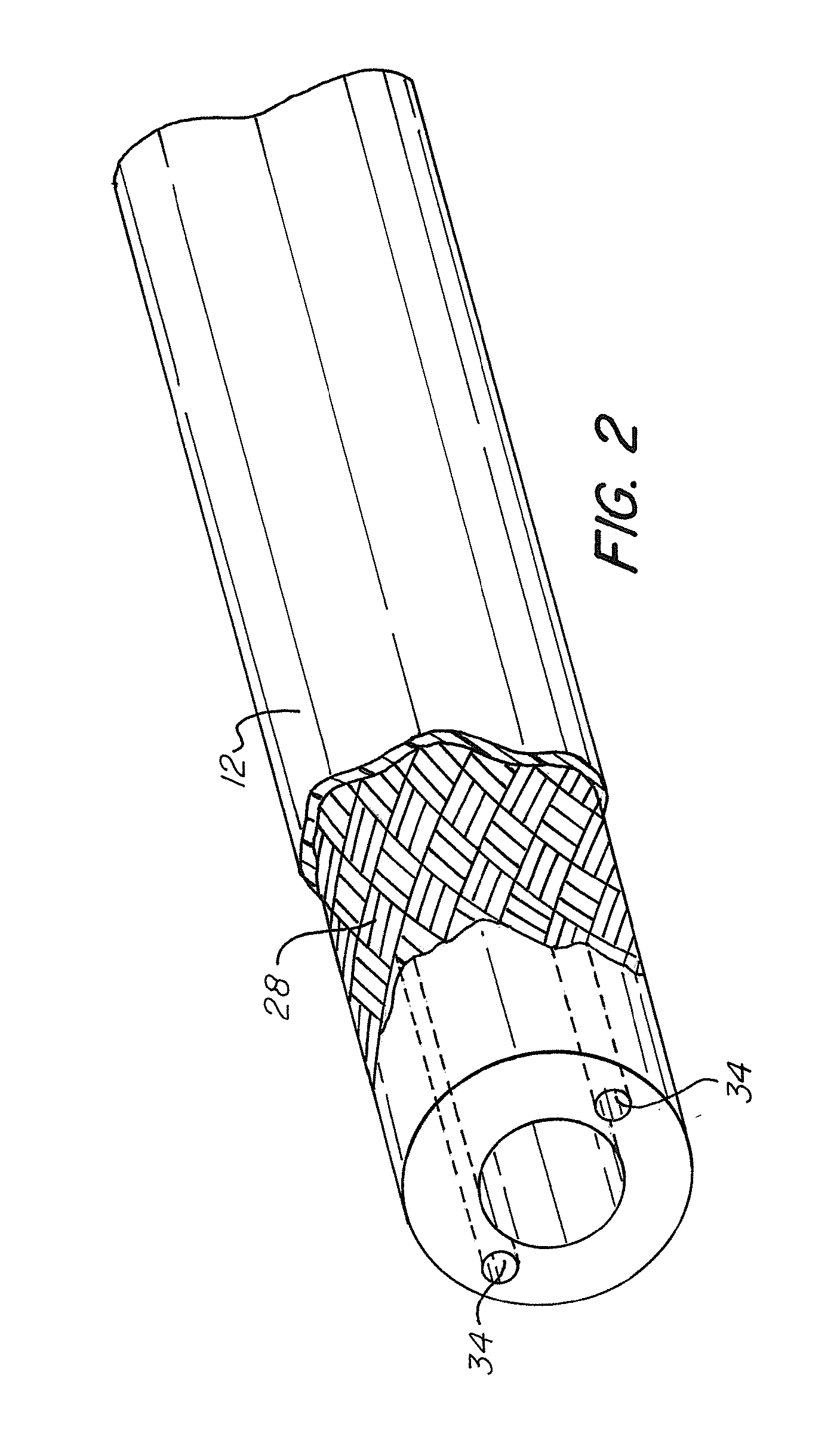
[0075]As shown in FIG. 1, a steerable catheter, generally indicated at reference character (10), includes an elongated catheter body (12) having a proximal end (16) and a distal end (14). The catheter body (12) has a generally cylindrical body with an inner lumen. The catheter body (12) has a longitudinal axis (X-X) along which the length of the catheter body is defined.

[0076]The elongated catheter body (12) may be constructed from any suitable rigid or semi-rigid material, such as, for example...


PUM


Abstract

A steerable catheter device includes a catheter body, a flexing tip member coupled to a distal end of the catheter body and having a wall with a first plurality of arcuate slits and a second plurality of arcuate slits, the first and second plurality of slits being diametrically opposed and alternating with each other, and an actuator that bends the flexing tip member, wherein at least a portion of the catheter body includes a braided sheath, and wherein each of the first and second plurality of slits has two ends and a center positioned midway between the two ends, and wherein all of the first plurality of slits have centers positioned along a first axis substantially parallel to the longitudinal axis of the catheter body and all of the second plurality of slits have centers positioned along a second axis substantially parallel to the longitudinal axis of the catheter body.

Description

FIELD OF THE INVENTION[0001]The present invention relates to systems and methods for moving a catheter in bodily cavities. More specifically, the present invention relates to a catheter having a flexing tip member, which allows the catheter to be steered.BACKGROUND OF THE INVENTION[0002]In general, catheters are used in medical procedures in which tubular structures, lumens, pleural cavities or spaces of the body, such as airways, vessels, organs and joints, are diagnostically examined and / or therapeutically treated. Catheters, which can be introduced into the body through a natural orifice or through an incision, can deliver imaging devices, surgical instruments, implants, fluids, drugs, pharmacologic materials, biologic materials, biologic agents and therapeutics to treat or remedy various pathologies found therein. Catheters also guide and deliver other components, such as guide wires, scaffolds and tools, to the intended site within the body.[0003]Flexible, semi-rigid and rigid ...

Claims


Application Information

Patent Timeline
IPC IPC(8): A61M25/01A61B1/045A61B1/005A61B1/06A61M25/00A61B1/05
CPCA61M25/0138A61M25/0053A61M25/0054A61M25/0147A61B1/051A61M2025/015A61B1/053A61B1/0676A61B1/045A61B1/0684A61B1/0057A61B1/0055A61B1/00096A61B1/00105A61B1/0052A61B1/05A61M25/005A61M25/0069A61M25/0136
Inventor GERRANS, LAWRENCE J.GUNDAY, ERHAN H.HSIA, ALEXTUNG, JESSIE
Owner SANOVAS
Why Eureka
Try Eureka