Method and apparatus for reducing frame error rate through signal power adjustment

a frame error rate and signal power adjustment technology, applied in the field of wireless communication systems, can solve the problems of increased latency, increased delay time, increased delay time, etc., and achieves the effect of reducing delay times that are both higher on average and have greater varian

Inactive Publication Date: 2001-10-02
QUALCOMM INC
View PDF19 Cites 71 Cited by
  • Summary
  • Abstract
  • Description
  • Claims
  • Application Information

AI Technical Summary

Problems solved by technology

However, these methods of achieving low FER cause increased latency due to the retransmission of data blocks.
Such increased latency is not acceptable when transmitting certain types of data, such as real time digitized voice, or any other type of latency sensitive da...

Method used


Image

  • Method and apparatus for reducing frame error rate through signal power adjustment
  • Method and apparatus for reducing frame error rate through signal power adjustment
  • Method and apparatus for reducing frame error rate through signal power adjustment

Examples


Embodiment Construction

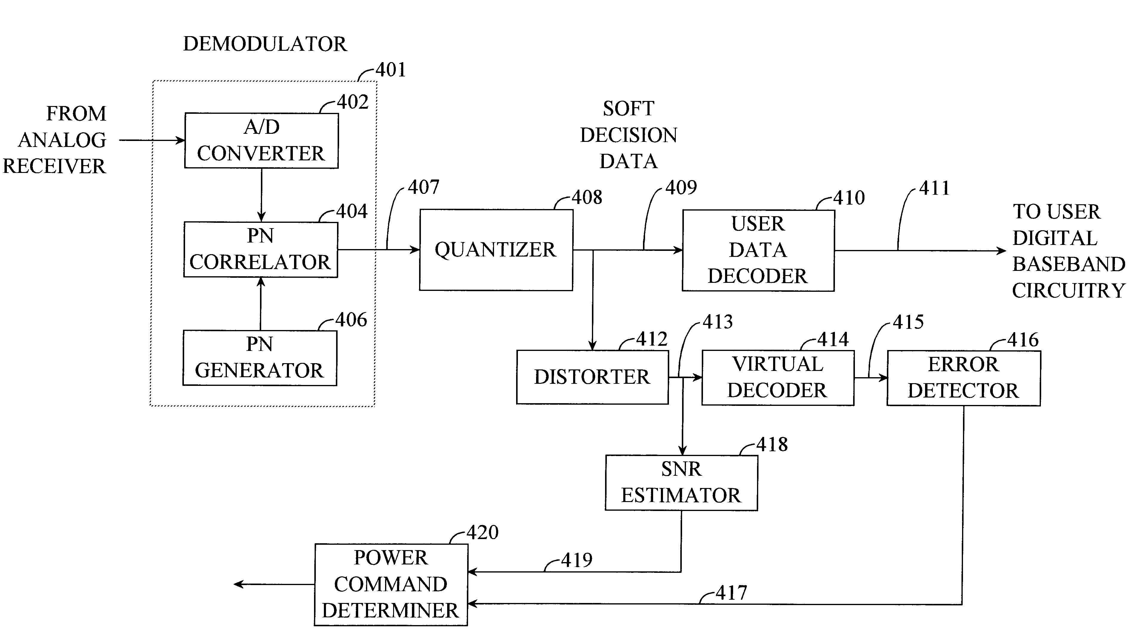
FIG. 4B illustrates an alternative power control scheme according to a preferred embodiment of the present invention. The power control scheme illustrated in FIG. 4B is similar to the power control scheme of FIG. 4A in that it includes demodulator 401, quantizer 408 (preferably, but not necessarily), user data decoder 410, error detector 416 and / or SNR estimator 418, and power command determiner 420. However, the embodiment of FIG. 4B differs in a few significant ways. First, the power control scheme of FIG. 4B also includes a distorter 412 and a virtual decoder 414. Additionally, in this embodiment, the input to SNR estimator is output 413 of distorter 412, rather than output 409 of quantizer 408 (or output 407 directly). Further, the input to error detector 416 is output 415 of virtual decoder 414, rather than output 411 (user data) of user data decoder 410.

It is noted that user data decoder 410 and virtual decoder 414 can be physically distinct components. Alternatively, data dec...


PUM


Abstract

A method and apparatus for controlling a signal transmission power. The method of the present invention includes the steps of demodulating a received signal to produce a demodulated signal and distorting the demodulated signal to produce a distorted demodulated signal. The demodulated signal can be distorted by, for example, adding noise. A signal quality measurement, such as signal-to-noise ratio, is then determined based on the distorted demodulated signal rather than the demodulated signal. An adjustment in the transmission power is then requested based on the signal quality measurement of the distorted demodulated signal.

Description

I. Field of the InventionThe present invention relates generally to a wireless communication system, and more specifically, to a method and apparatus for reducing frame error rate (FER) in a wireless communications system.II. Related ArtWhen delivering data over a wireless link that has a relatively poor FER (for example, greater than 1%), many methods of retransmitting data exist for achieving as low a FER as a data service demands. For example, a cyclic redundancy check (CRC) can be performed at a receiving end of a link to check the integrity of a block of data. CRC is a well known method of establishing that data was correctly received in data communications. A CRC character is generated at a transmitting device and appended to a data block. The receiving end makes a similar calculation and compares its results with the added CRC character. If there is a difference, the receiving end requests retransmission of the data block.For example, the use of protocols such as Automatic Re...

Claims


Application Information

Patent Timeline
IPC IPC(8): H04B7/185H04B7/005H04L1/00H04B7/26
CPCH04B7/18543H04W52/18H04W52/20H04W28/04
Inventor SCHIFF, LEONARD N.
Owner QUALCOMM INC
Why Eureka
Try Eureka