Method and apparatus for correcting faults in a passive optical network

a passive optical network and fault correction technology, applied in electromagnetic network arrangements transmission monitoring/testing/fault-measurement systems, etc., can solve problems such as system failure or rogue ont condition, failure of particular hardware or type, and/or communication signals corrupted upstream and/or downstream

Active Publication Date: 2012-01-03
TELLABS PETALUMA
View PDF2 Cites 174 Cited by
  • Summary
  • Abstract
  • Description
  • Claims
  • Application Information

AI Technical Summary

Problems solved by technology

Various components of the optical distribution network (ODN), including the OLT, optical components, and ONT(s), can malfunction in such a way that upstream and / or downstream communications signals become corrupted.
This can make it difficult for the receiver of that signal, either the ONT or OLT, to communicate consistently and may result in misinterpreted commands that disrupt other ONT's communications, resulting in a system failure or rogue ONT condition.
Existing error detection techniques, such as those described in the various PON protocols, may not detect particular hardware failures, or if detected (e.g., by system failure), the particular hardware failure or type may not be identified.
For example, in certain situations, certain ONT faults or errors may trigger a failure mechanism in the OLT, causing a loss of connectivity between the OLT and one or more ONTs.
These types of faults or errors may occur after many days of operations and are not detectable using standards-based error detection methods.

Method used


Image

  • Method and apparatus for correcting faults in a passive optical network
  • Method and apparatus for correcting faults in a passive optical network
  • Method and apparatus for correcting faults in a passive optical network

Examples


Embodiment Construction

[0012]A description of example embodiments of the invention follows.

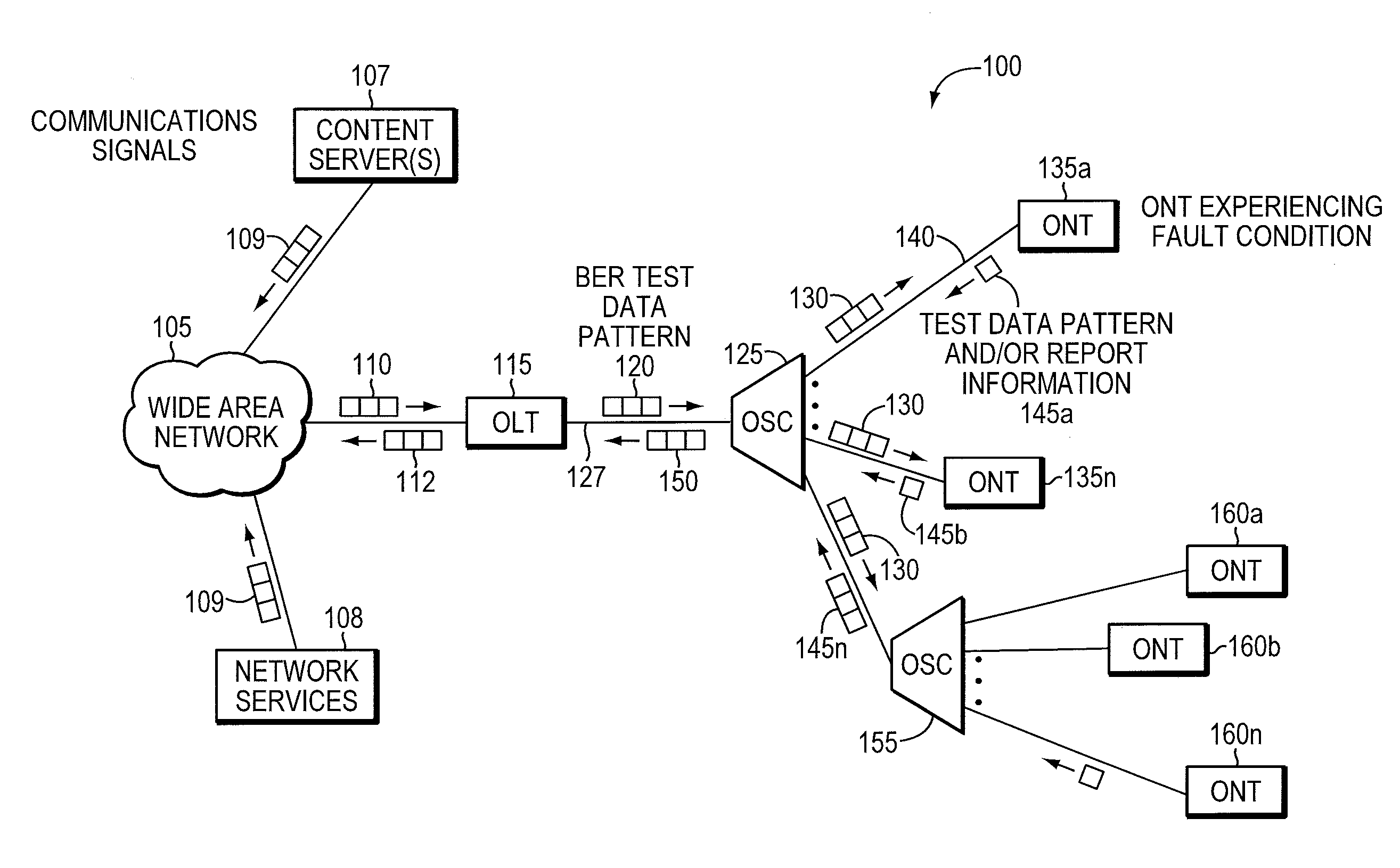
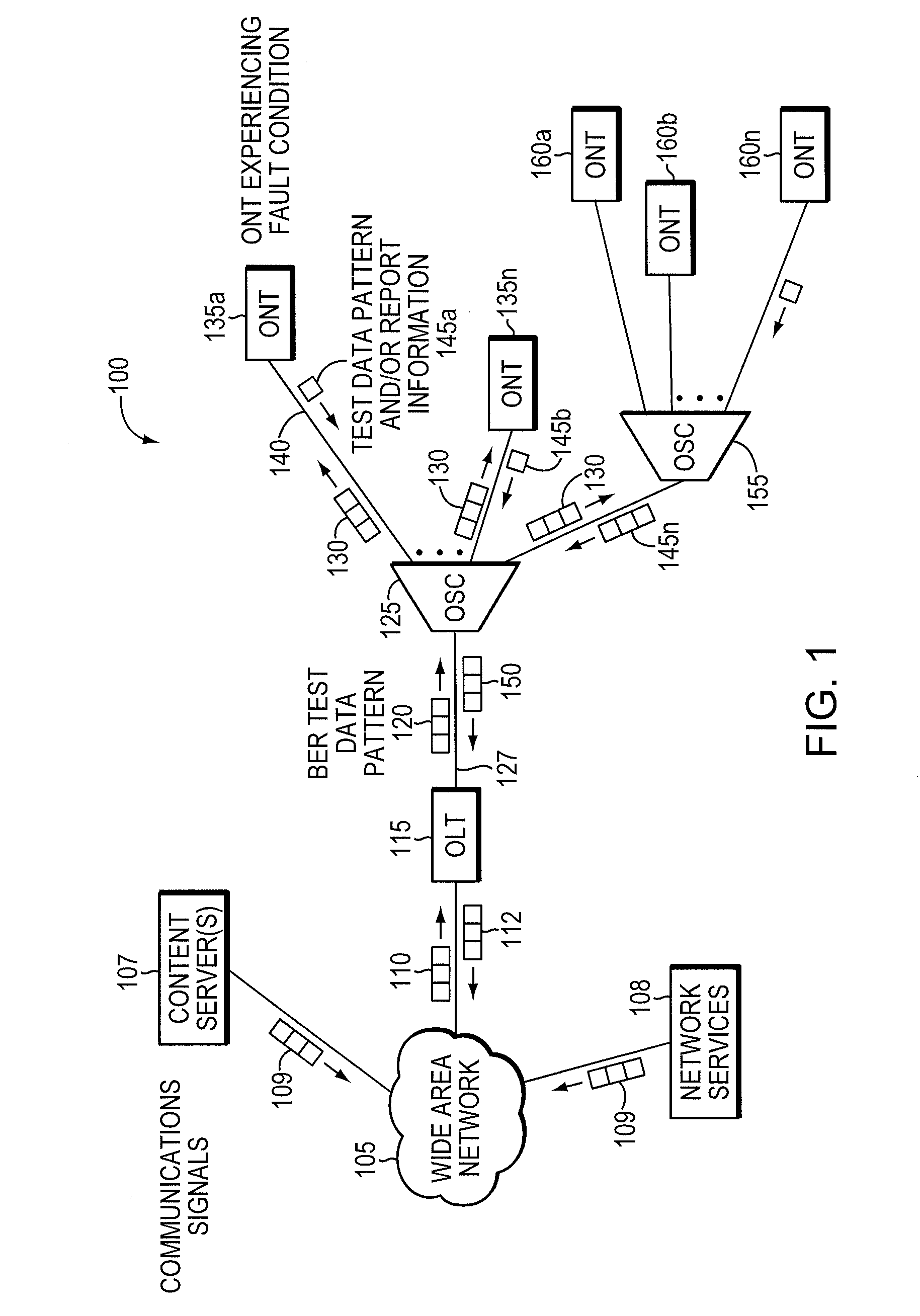
[0013]FIG. 1 is a network diagram of a passive optical network (PON) 100 illustrating aspects of an example embodiment of the invention. The PON 100 includes an optical line terminal (OLT) 115, an optical splitter / combiner (OSC) 125, and at least one optical network unit (ONT) 135a-n, 160a-n. In other network embodiments, optical network units (ONUs) (not shown) may be in optical communication with multiple ONT(s) 135a-n, 160a-n that are directly in electrical communication with end user equipment, such as routers, telephones, home security systems, and so forth (not shown). As presented herein, ONU's are typically found at a curb near premises, and ONT(s) extend to a premise, but both generally behave the same with respect to embodiments of this invention. Data communications 110 may be transmitted to the OLT 115 from a wide area network (WAN) 105. Content server(s) 107 or other network services 108 provide communi...


PUM


Abstract

Component malfunctions in passive optical networks (PON) can increase bit error rates and decrease signal-to-noise ratio of communications signals. These faults may cause the receivers of the signals, either the optical line terminal (OLT) or optical network terminals (ONTs), to experience intermittent faults and / or may result in misinterpreted commands that disrupt other ONT's communication, resulting in a rogue ONT condition. Existing PON protocol detection methods may not detect these types of malfunctions. An embodiment of the present invention identifies faults in a PON by transmitting a test series of data patterns via an optical communications path from a first optical network node to a second optical network node. The test series is compared to an expected series of data patterns. An error rate may be calculated as a function of the differences between the test series and expected series. The error rate may be reported to identify faults in the PON. Through use of the embodiment, network faults can be identified and optionally automatically corrected, saving a network service provider from expending technician time and maintaining an operating state of the network.

Description

BACKGROUND OF THE INVENTION[0001]In a passive optical network (PON), multiple optical network terminals (ONTs) or optical network units (ONUs) transmit data to an optical line terminal (OLT) using a common optical wavelength and fiber optic media. Various components of the optical distribution network (ODN), including the OLT, optical components, and ONT(s), can malfunction in such a way that upstream and / or downstream communications signals become corrupted. This can make it difficult for the receiver of that signal, either the ONT or OLT, to communicate consistently and may result in misinterpreted commands that disrupt other ONT's communications, resulting in a system failure or rogue ONT condition.[0002]Existing error detection techniques, such as those described in the various PON protocols, may not detect particular hardware failures, or if detected (e.g., by system failure), the particular hardware failure or type may not be identified. For example, in certain situations, cer...

Claims


Application Information

Patent Timeline
Patent Type & Authority Patents(United States)
IPC IPC(8): H04B10/08
CPCH04B10/073H04B10/272
Inventor DELEW, DAVID A.O'CONNOR, PAUL E.LARVENZ, ROBERT S.
Owner TELLABS PETALUMA
Why Eureka
Try Eureka