Piston pump

a piston pump and piston technology, applied in the direction of positive displacement liquid engines, braking systems, liquid fuel engines, etc., can solve the problems of complex piston manufacturing and high cos

Inactive Publication Date: 2001-10-16
ROBERT BOSCH GMBH
View PDF10 Cites 56 Cited by
  • Summary
  • Abstract
  • Description
  • Claims
  • Application Information

AI Technical Summary

Problems solved by technology

The manufacture of the piston is...

Method used


Image

  • Piston pump
  • Piston pump
  • Piston pump

Examples


Embodiment Construction

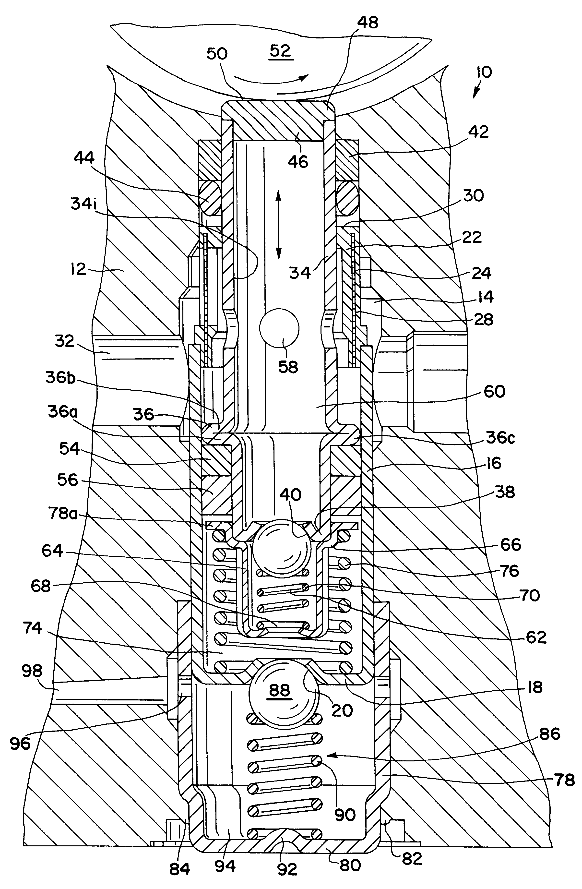
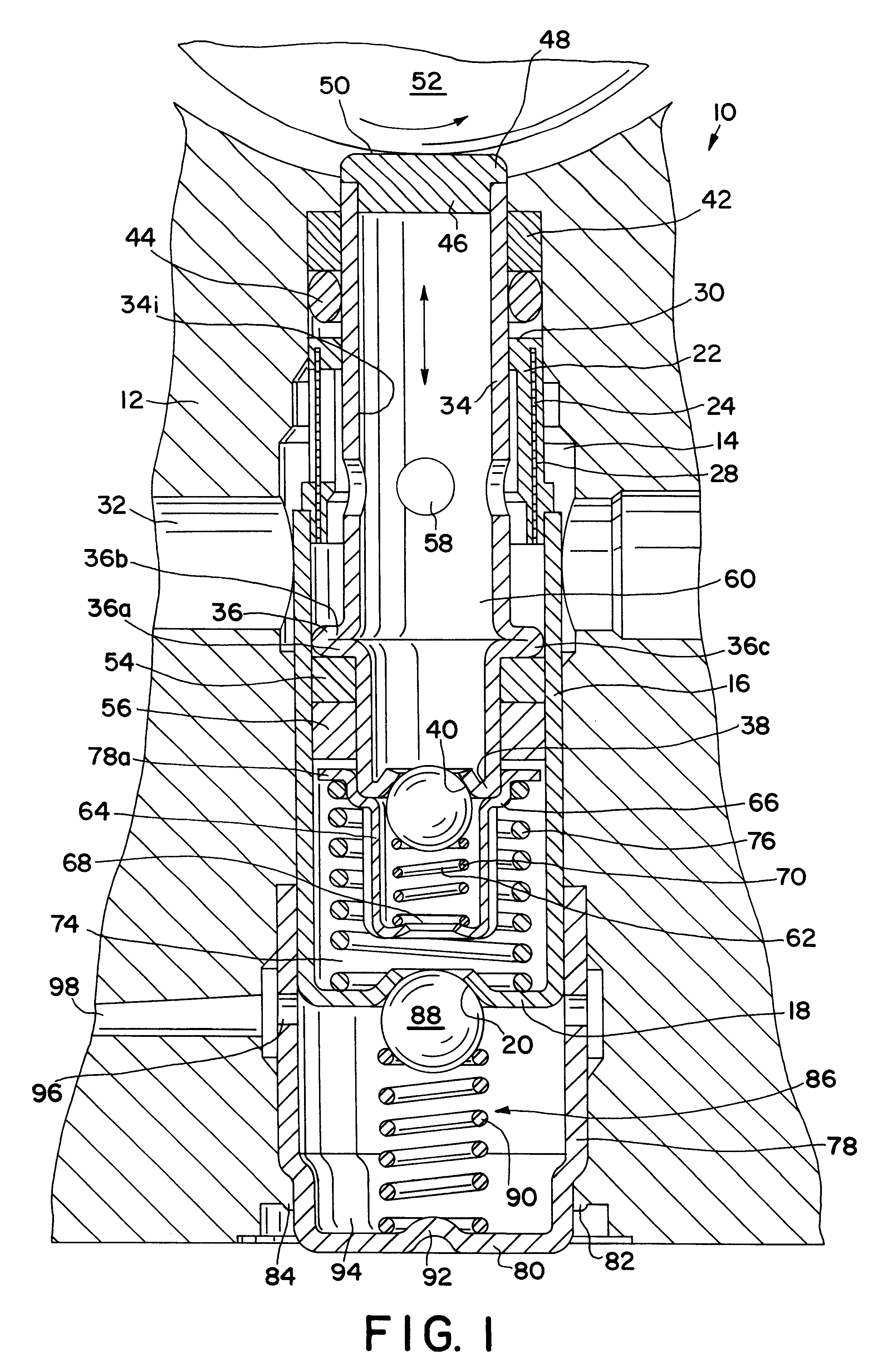
The piston pump 10 according to the invention shown in FIG. 1 is accommodated in a hydraulic block 12 of a slip-controlled vehicle brake system that is not shown in detail. Other hydraulic components, not shown, for example solenoid valves of the slip-controlled vehicle brake system, are inserted into the hydraulic block 12, of which only a fraction encompassing the piston pump 10 is shown for the sake of clarity, and these hydraulic components are hydraulically connected to one another and to the piston pump 10 by means of the hydraulic block 12. The hydraulic block 12 is hydraulically connected to a master cylinder, not shown, and wheel brake cylinders, not shown, are connected to the hydraulic block. The hydraulic block 12 constitutes a pump housing 12 of the piston pump 10 according to the invention and will be referred to as such below.

A cylinder bore 14 is let into the pump housing 12 and a bushing 16 is press-fitted into this cylinder bore. The bushing 16 is a cylindrical, tu...


PUM


Abstract

The invention relates to a piston pump for a slip-controlled, hydraulic vehicle brake system. In order to be able to simply and inexpensively produce the piston pump as a stepped piston pump, the invention embodies a piston as a tubular deep drawn part made of sheet metal, with an outwardly protruding circumferential bead. The bead is produced by axially compressing the piston. The bead constitutes an axial support for a guide ring and sealing ring placed onto the piston. A disk-shaped, abrasion resistant striking piece is press-fitted into an open end of the tubular piston, and is used by the piston for resting against a circumference of a cam element used for the stroke drive.

Description

PRIOR ARTThe invention relates to a piston pump which is provided for use in a slip-controlled or electrohydraulic vehicle brake system.A multitude of such piston pumps have been disclosed. One such example is DE 40 27 794 A1. The known piston pump has a pump housing into which a bushing is inserted which contains an axially movable piston which can be driven into a reciprocating stroke motion. The piston is a part that is produced in a cutting fashion by means of boring and turning. The manufacture of the piston is therefore complex and cost intensive.ADVANTAGES OF THE INVENTIONIn the piston pump according to the invention, the piston is embodied as tubular and its manufacture takes place for example by means of deep drawing. By means of shaping, for example by means of axially compressing the tubular piston, an outwardly protruding bead is produced on the piston, and this bead constitutes an axial support for a sealing ring or a guide ring of the piston. First, the invention has t...

Claims


Application Information

Patent Timeline
IPC IPC(8): B60T8/40F04B53/10F04B53/14F04B53/00F04B53/12F04B1/04F04B1/00F04B11/00B60T17/00F04B1/047F04B1/053
CPCB60T8/4031F04B1/0408F04B11/0016F04B53/126F04B53/14
Inventor SCHULLER, WOLFGANGMAYER, FRANZSCHILLER, CHRISTIANE
Owner ROBERT BOSCH GMBH
Why Eureka
Try Eureka