Compiling method for generating target program in accordance with target processor type, compiling device, recording medium with compiling program recorded therein and recording medium with conversion table used in compiling recorded therein

a technology of target processor and target processor type, which is applied in the direction of program code transformation, instruments, computing, etc., can solve the problems of increasing the amount of generation code table, disadvantageous increase of operations necessary for generating generation code table, and first conventional system cannot be used

Inactive Publication Date: 2001-10-16
RENESAS ELECTRONICS CORP
View PDF15 Cites 29 Cited by
  • Summary
  • Abstract
  • Description
  • Claims
  • Application Information

AI Technical Summary

Problems solved by technology

When a large number of types of target processors are to be handled, the amount of the generation code table is enormously increased, and an amount of operations necessary for generating the generation code table is disadvantageously increased.
Therefore, the first conventional system can only be used for a target processor group of a limited type in which the way of development is the same as a source program format.
For example, in the system, a program (target program) for a microprocessor manufactured by a specified maker can be generated, but a program for a microprocessor manufactured by another maker cannot be generated.
Therefore, the first conventional system has a problem that the types of target processors are limited.
As a result, when a large number of types of target processors are to be handled, the amount of the code generating skeleton table disadvantageously becomes enormous.
Furthermore, when the amount of code generating skeleton table is enormous, the amount of operations necessary for preparing the code generating skeleton table is disadvantageously increased.

Method used


Image

  • Compiling method for generating target program in accordance with target processor type, compiling device, recording medium with compiling program recorded therein and recording medium with conversion table used in compiling recorded therein
  • Compiling method for generating target program in accordance with target processor type, compiling device, recording medium with compiling program recorded therein and recording medium with conversion table used in compiling recorded therein
  • Compiling method for generating target program in accordance with target processor type, compiling device, recording medium with compiling program recorded therein and recording medium with conversion table used in compiling recorded therein

Examples


first embodiment

In a first embodiment, a compiling method, compiling device, recording medium with a compiling program stored therein, and a recording medium with a conversion table stored therein according to the present invention will be described.

First, a configuration of the first embodiment will be described with reference to FIGS. 1 and 2.

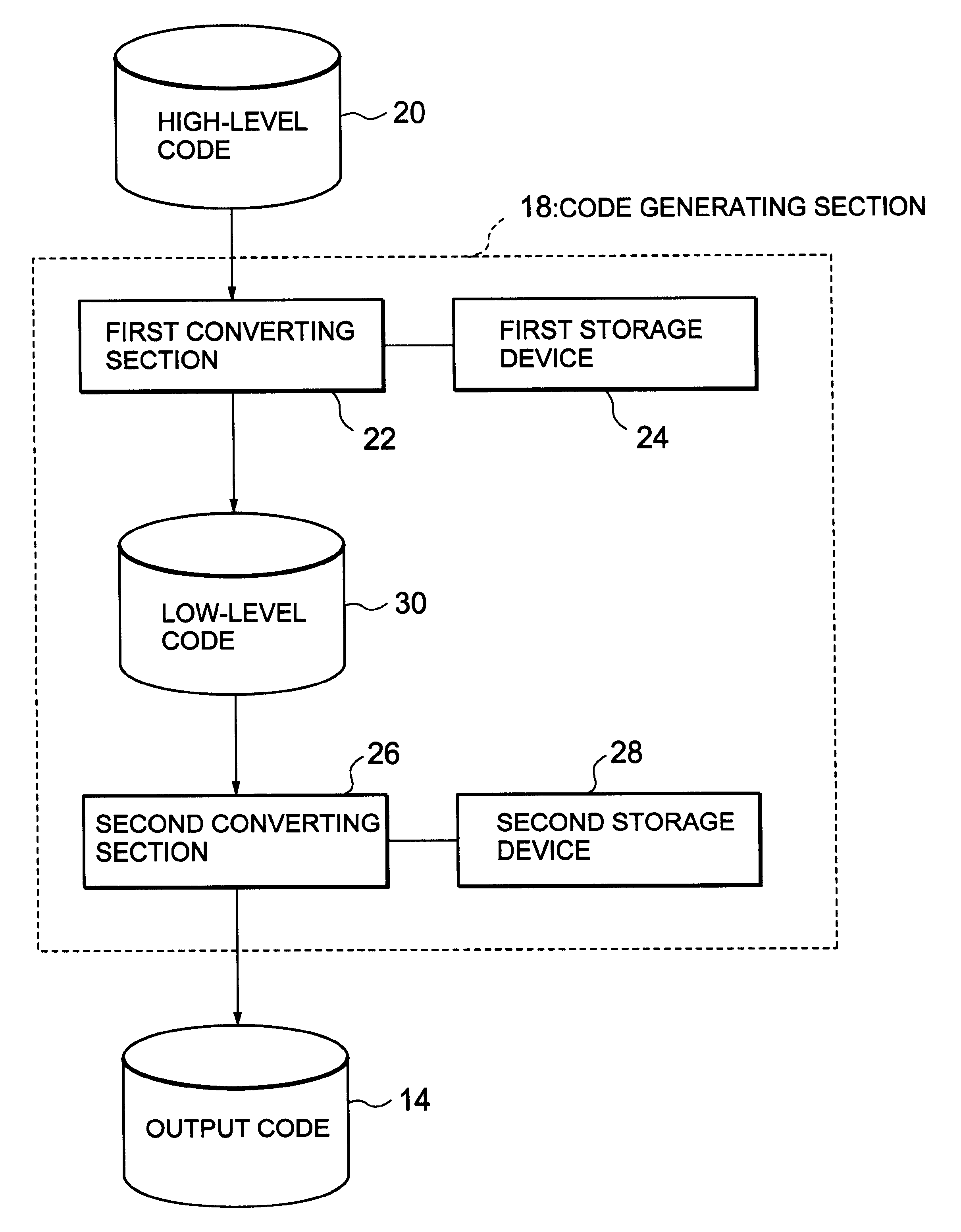
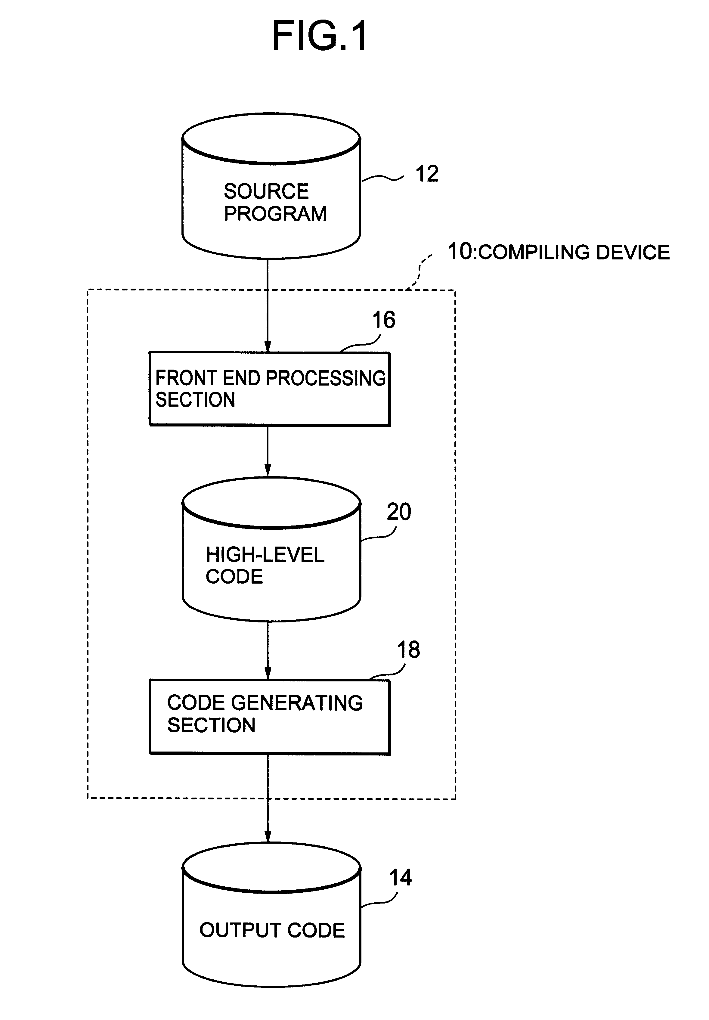
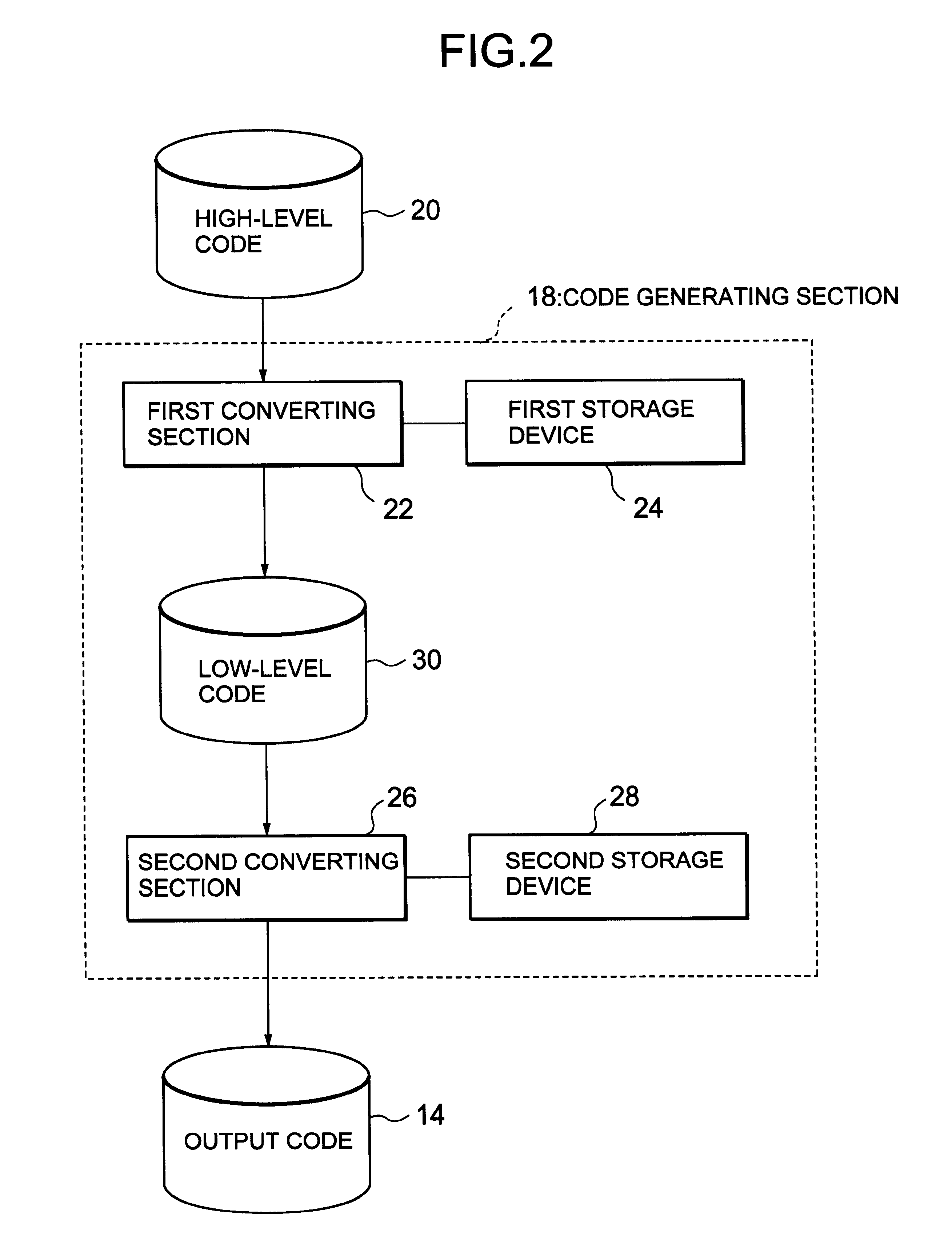
FIG. 1 is a block diagram showing an entire configuration of the first embodiment. FIG. 2 is also a block diagram showing a configuration of a code generating section.

Referring to FIG. 1, a compiling device 10 of the first embodiment is a device for generating a code 14 for a target program operated in a target processor (hereinafter referred to as the output code 14) from a source program 12, comprising a front end processing section 16, and a code generating section 18.

The front end processing section 16 performs a semantic analysis of the inputted source program 12 to generate a high-level intermediate language code 20 independent of a target program type...

second embodiment

A second embodiment of the present invention will next be described with reference to FIG. 9. FIG. 9 is a block diagram showing a configuration of code generating section 18a in the second embodiment.

In the second embodiment, first and second conversion tables 32, 34 are stored in external storage devices. Specifically, the first conversion table 32 is stored in a first storage device 40. Moreover, the second conversion table 34 is stored in a second storage device 42.

Here, to store the conversion table in the external storage device includes, for example, a case where the conversion table comprises a program or a file separate from the program for operating the code generating section. Moreover, the first converting section 22 may be connected to the first external storage device 40, for example, via a communication channel. Furthermore, the second converting section 26 may also be connected to the second external storage device 42, for example, via the communication channel.

Additi...

third embodiment

In a third embodiment, an example of generating output codes from high-level code "ADD_M_M mem1, mem2, reg$" will be described. High-level code command "ADD_M_M" in the high-level code indicates a function of loading a register with two pieces of data on a memory to perform addition. The high-level code command is provided with operands "mem1", "mem2", and "reg$". The "mem1" indicates the data on a first memory, while "mem2" indicates the data on a second memory. Moreover, "reg$" indicates the register for storing results.

When the high-level code is represented, for example, by output codes for target program A, they are "ld.w mem1, treg1", "ld.w mem2, treg2" and "add reg1, treg2, reg$". In this case, "ld.w" indicates a command for loading wide size data, "treg1" and "treg2" indicate registers for temporarily storing intermediate results, and "add" indicates a command for addition.

Moreover, when the high-level code is represented, for example, by output codes for target program B, t...


PUM


Abstract

There is disclosed a compiling method of generating a code of a target program operable in a desired target processor, in which an amount of operations required for the code generation is reduced. Specifically, a code generating section 18 comprises a first converting section 22 and a second converting section 26. The first converting section 22 refers to a first conversion table stored in a first storage device 24 to generate a low-level code 30 from a high-level code 20, while the second converting section 26 refers to a second conversion table stored in a second storage device 28 to generate an output code 14 from the low-level code 30. In the second conversion table, output codes indicating the same or similar function are associated to the common low-level code.

Description

1. Field of the InventionThe present invention relates to a method of compiling a source program to generate a mechanical level program (hereinafter referred to as the target program), particularly to a method in which the target program can be generated in accordance with a type of processor (hereinafter referred to as the target processor) for operating the target program from one source program. The present invention also relates to a device for realizing the method, a recording medium in which a program for allowing a computer to execute a processing based on the method is stored, and a recording medium in which a conversion table for use in the processing based on the method is recorded.2. Description of the Related ArtAn example of a conventional compiling system is described in Japanese Patent Application Laid-Open No. Hei 6-332719. The compiling system will briefly be described as a first conventional example with reference to FIG. 13. FIG. 13 is a flowchart showing the firs...

Claims


Application Information

Patent Timeline
Patent Type & Authority Patents(United States)
IPC IPC(8): G06F9/45
CPCG06F8/447G06F8/47
Inventor MIYAMOTO, TAKASHI
Owner RENESAS ELECTRONICS CORP
Why Eureka
Try Eureka