Motorized self-cleaning oven latch

a self-cleaning, oven technology, applied in the field of oven latches, can solve the problems of oven unusability, door locking, motor failure,

Inactive Publication Date: 2001-11-13
EASTERN COMPANY THE
View PDF17 Cites 92 Cited by
  • Summary
  • Abstract
  • Description
  • Claims
  • Application Information

AI Technical Summary

Benefits of technology

In another embodiment of the invention, the repair guide portion of the guide slot is not separated from the normal guide portion of the guide slot. Instead, a spring is connected to the latch arm or the rod to keep the end of the latch arm guided by the normal guide portion of the guide

Problems solved by technology

One problem with conventional motorized latches is that the motor may fail, leaving the door locked even after the temperature within the oven has dropped to a safe level.
Failure of the motor when the latch is in the locked position leaves the oven unusable, even when it is not in the self-cleaning cycle.
Another problem with prior art latches is that the s

Method used


Image

  • Motorized self-cleaning oven latch
  • Motorized self-cleaning oven latch
  • Motorized self-cleaning oven latch

Examples


Embodiment Construction

)

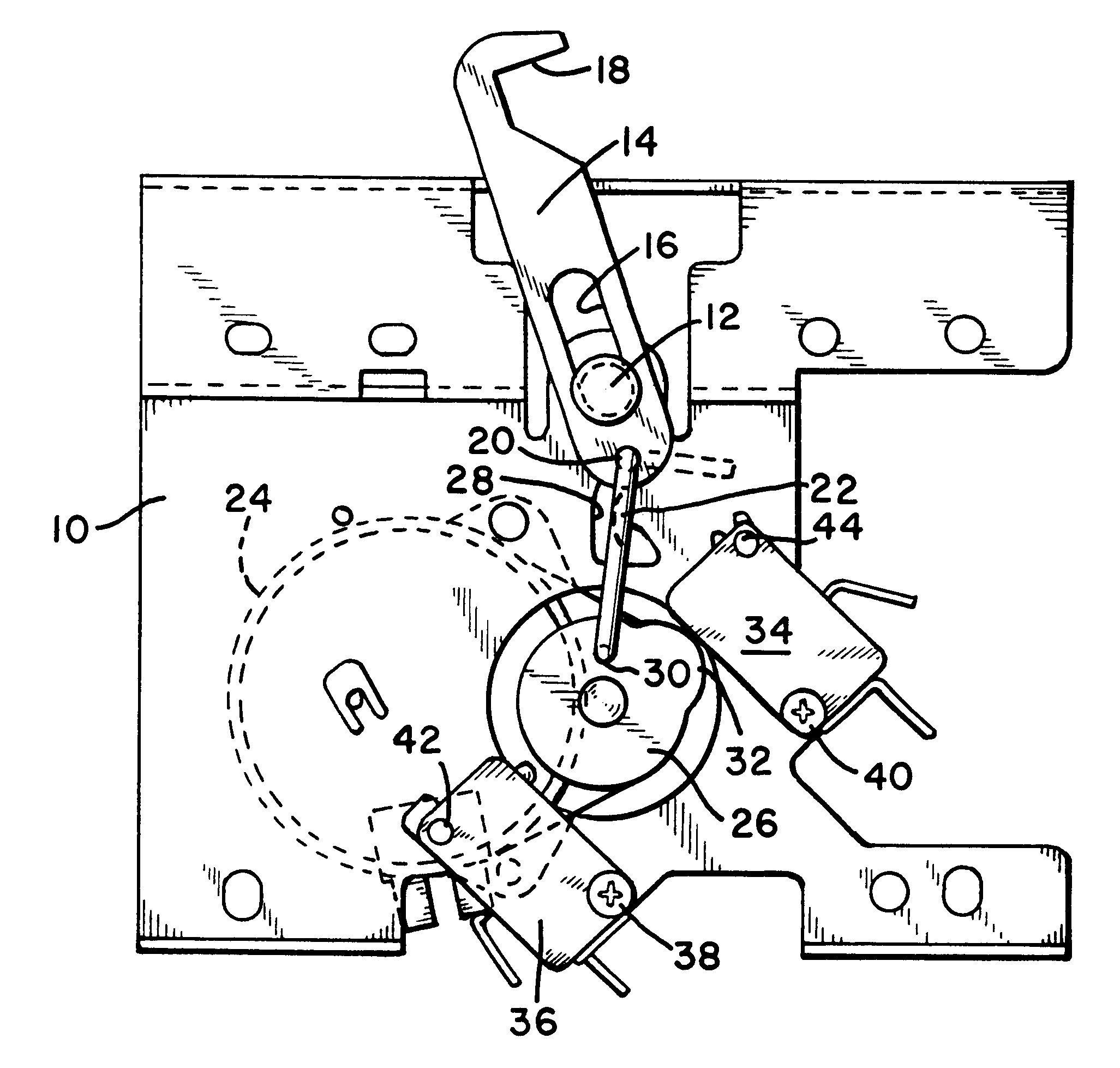
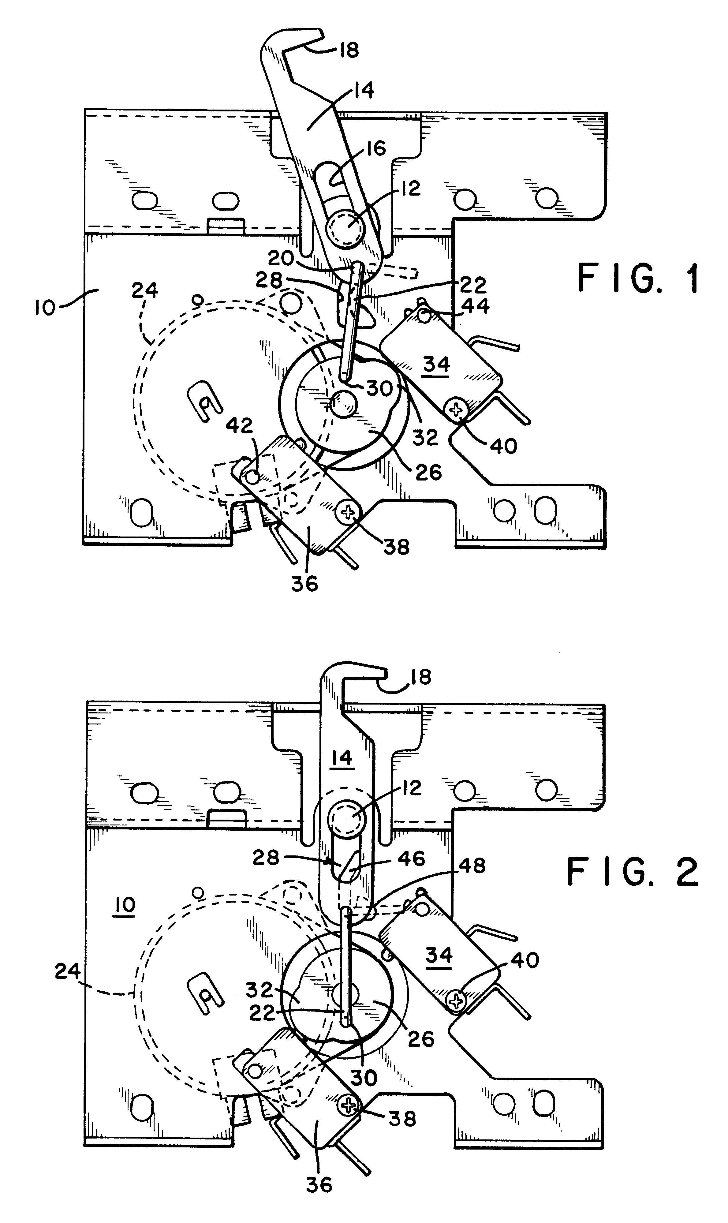
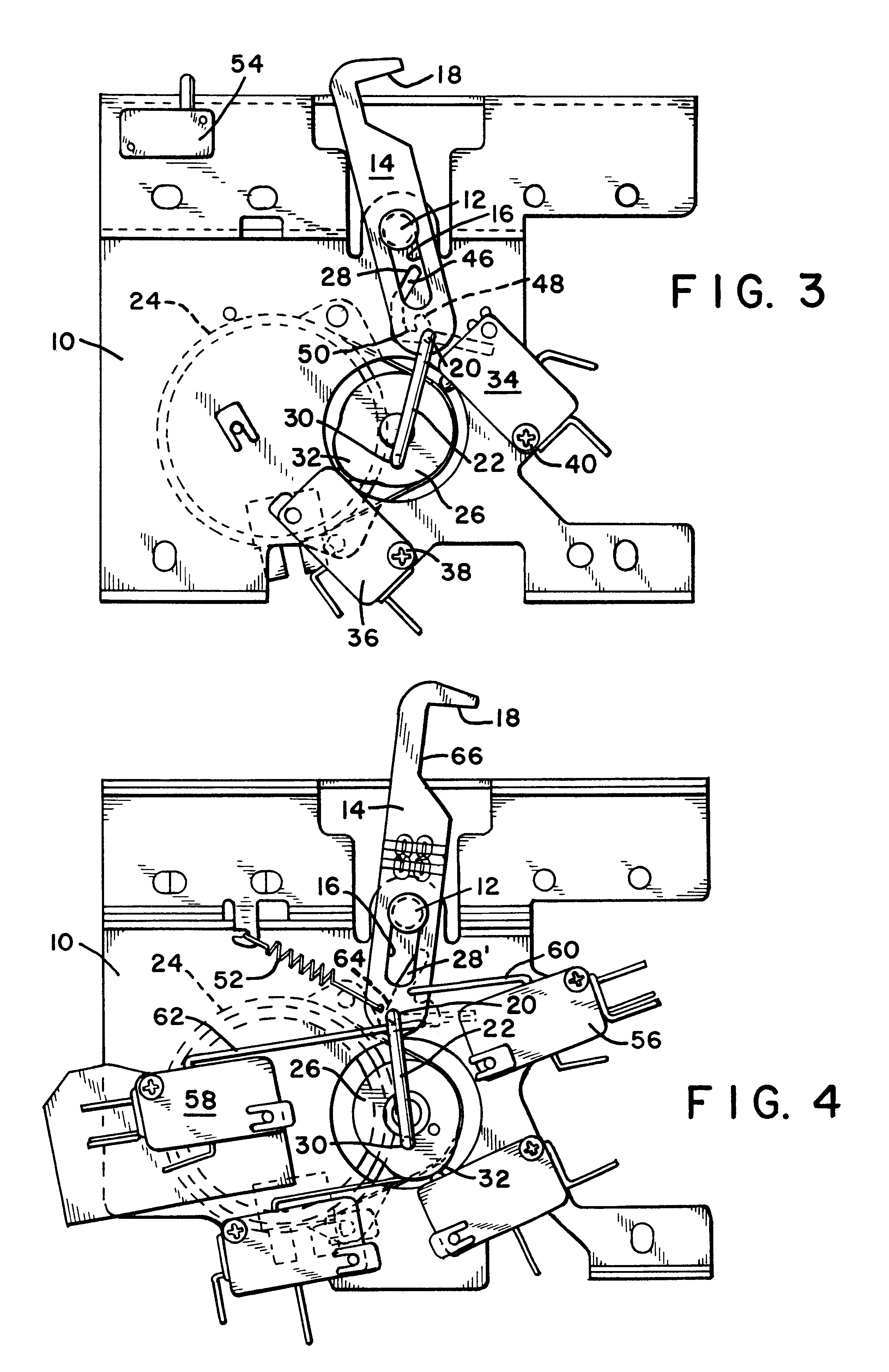
In describing the preferred embodiment of the present invention, reference will be made herein to FIGS. 1-5 of the drawings in which like numerals refer to like features of the invention.

Referring to FIG. 1, the present invention comprises an oven latch including a base 10, a pivot 12 mounted on the base and a latch arm 14. The latch arm 14 includes a slot 16, a hook 18 at one end for engaging an oven door and an opening 20 at the opposite end for receiving an end of rod 22. Pivot 12, which may be a screw or a rivet, includes a head having a diameter that larger than the width of slot 16 such that the latch arm 14 is free to slide relative to pivot 12 along the length of slot 16 and to pivot or rotate relative to the pivot. The sliding and pivoting motion of the latch arm 14 is controlled by rod 22. More specifically, the sliding and pivoting motion of the latch arm 14 is controlled by how rod 22 moves opening 20 in the end of the latch arm relative to the location of pivot 12.

The ...


PUM


Abstract

An oven latch includes a base, a pivot, and a latch arm with a slot that engages the pivot and allows the latch arm to slide and rotate relative to the pivot. A motor mounted on the base rotates a cam, and a rod connected between the cam and the latch arm closes the latch when the cam turns, thereby pivoting the latch arm closed to engage the oven door and sliding the latch arm inwards along the latch arm slot to pull in the door. The pivoting and sliding motion of the latch arm is controlled by a guide slot formed in the base having a normal guide portion and a repair guide portion. During normal operation, an end of the rod moves along the normal guide portion of the guide slot. If the motor fails, the end of the rod may be manipulated into the repair guide portion of the guide slot to open the latch when the motor and cam are in the closed position.

Description

1. Field of the InventionThe present invention relates to oven latches used to latch an oven door closed during a self-cleaning cycle. More specifically, the present invention relates to motorized self-cleaning oven latches used with electronic oven controls.2. Description of Related ArtSelf-cleaning ovens reach a very high temperature during the cleaning operation. To prevent injury, safety standards require the door to be automatically latched when the oven is above a safe operating temperature to prevent the door from being opened. In some ovens, the automatic latching is achieved by moving a locking element with a bimetallic coil responsive to the temperature reached by an oven during the self-cleaning cycle. However, many modern ovens use digital electronic controls and in these designs the latching is preferably accomplished with a motorized latch that operates directly under electronic control.One problem with conventional motorized latches is that the motor may fail, leaving...

Claims


Application Information

Patent Timeline
IPC IPC(8): E05B47/00F24C15/02E05B63/00E05C5/00
CPCE05B47/0012F24C15/022E05B63/0069E05B2047/0024E05B2047/0086E05C5/00Y10S292/69Y10T292/1082
Inventor SWARTZELL, SCOTT D.
Owner EASTERN COMPANY THE
Why Eureka
Try Eureka