
Snap-fit catalyst device

a catalyst device and catalytic converter technology, applied in the direction of domestic stoves or ranges, heating types, separation processes, etc., can solve the problems of uneconomical and labor-intensive catalytic converter installation with a separate metal can, and achieve the effect of reducing smoke and volatile organic compounds

Inactive Publication Date: 2007-03-01
APPL TECH LLP
View PDF5 Cites 0 Cited by
  • Summary
  • Abstract
  • Description
  • Claims
  • Application Information

AI Technical Summary

Benefits of technology

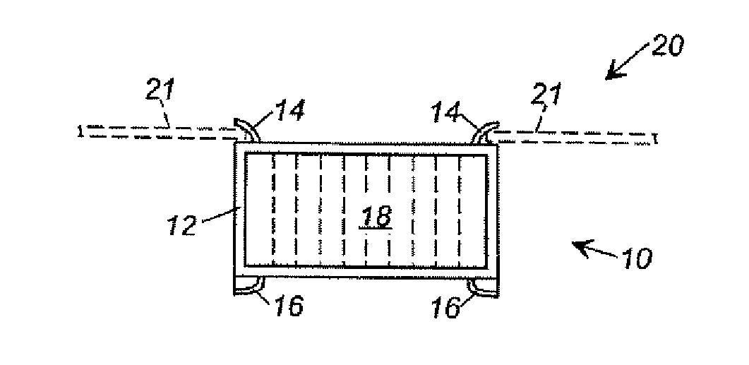
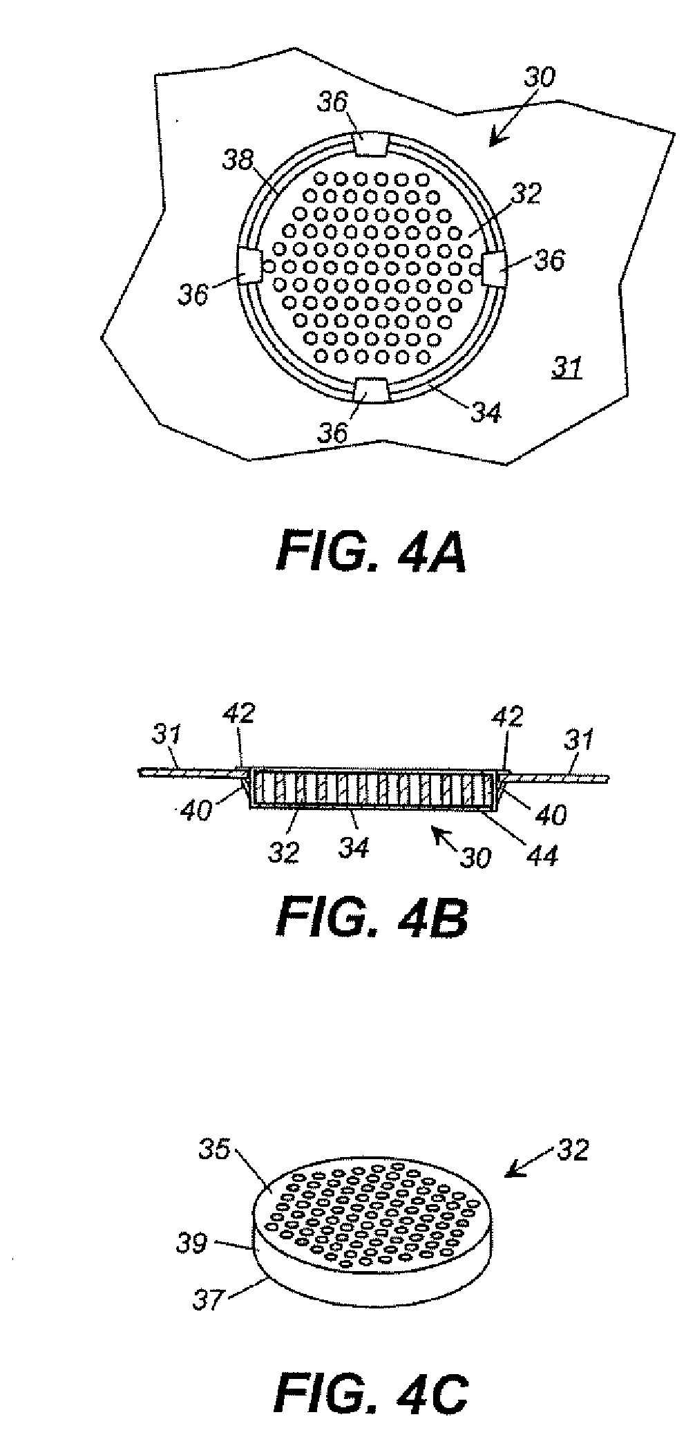
[0012] In still another embodiment, a method is provided for reducing smoke and volatile organic compounds present in a gas flowing into a vent, which could be part of a kitchen range which comprises a self-cleaning oven. In one embodiment, the method comprises flowing the gas through apertures in a mesh of metal strands in a dish-shaped body of a catalytic converter device, at least the surface of the mesh of metal strands comprising a catalyst material, to oxidize smoke and volatile organic compounds present in the gas, wherein the body is secured within an orifice in the gas vent by the cooperation of one or more locking tabs and a flange which extend from sidewalls of the body.
[0014] The catalytic converter devices can be used in a variety of residential, commercial, or industrial ovens, as well as other devices or systems in which catalytic conversion of a flue gas is desirable. Self-cleaning kitchen ovens are preferred. The devices are used to reduce smoke and volatile organic compounds present in an exhaust gas flowing from an oven, such as in an exhaust gas vent.

Problems solved by technology

In addition, catalyst installation with a separate metal can is labor-intensive and uneconomical.

Method used


Image

  • Snap-fit catalyst device
  • Snap-fit catalyst device
  • Snap-fit catalyst device

Examples


Embodiment Construction

[0023] Improved catalytic converter devices and exhaust vents have been developed for easier and more economical assembly and installation into a self-cleaning kitchen range or other self-cleaning oven. The present devices save space, installation time, and cost over commercially available catalytic converters.

The Catalytic Converter Device

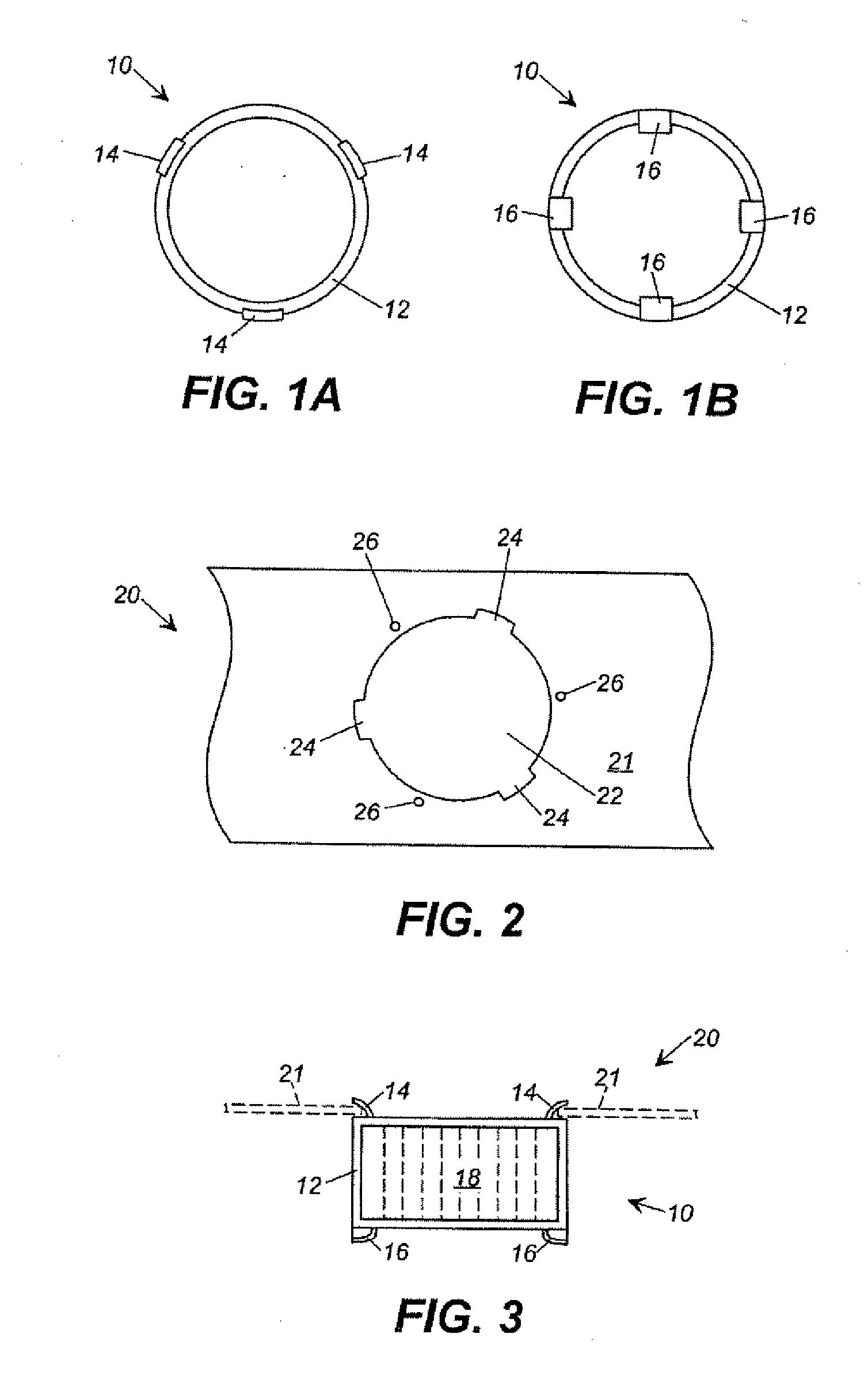
[0024] The catalytic converter device includes a substrate, a catalyst material on the surface of the substrate (e.g., as a coating), and a means for securing the substrate into an orifice of a gas vent (e.g., an oven vent), such that exhaust gases flowing through the vent will pass through apertures in the device to oxidize smoke and volatile organic compounds present in the gas. The substrate can be in the form of a mesh of metal strands or it can in the form of a ceramic body. The means for securing the metal mesh substrate / catalyst can be an integral feature built into the substrate, or it can be a mounting ring. The means for securing the ...


PUM

PropertyMeasurementUnit
diameteraaaaaaaaaa
thickaaaaaaaaaa
shapeaaaaaaaaaa

Abstract

A catalytic converter device, useful with a self-cleaning oven, is provided. The device includes (a) a dish-shaped body formed of a mesh of metal strands, the body having a base member, sidewalls projecting from the base member, and a flange extending out from the sidewalls, the mesh having a plurality of apertures therethrough; (b) a catalytic material on at least the surface of the mesh; and (c) one or more locking tabs extending from the sidewalls, wherein the locking tabs and flange cooperate to secure the device within an orifice of a gas vent so exhaust gases will pass through the apertures. The locking tabs can be formed by punching a hole in the sidewall, such that each locking tab remains integral with the sidewall, the locking tab projecting from an edge of the hole distal the flange and at angle toward the flange.

Description

CROSS-REFERENCE TO RELATED APPLICATIONS [0001] This is a continuation-in-part of U.S. application Ser. No. 09 / 827,473, filed Apr. 6, 2001, now pending. That application is incorporated herein by reference.BACKGROUND OF THE INVENTION [0002] The devices and methods described herein are generally in the field of catalytic converter-type smoke eliminators, such as found in self-cleaning ovens. [0003] Self-cleaning ovens clean by heating the oven above normal cooking temperatures to bum off and eliminate the residues created in the oven during normal cooking. The organic cooking residues oxidize and evolve as smoke and vapors, which comprise volatile organic compounds (VOCs) and particulate matter. Standard commercially available ovens include catalytic converters. These catalytic converters complete the oxidation process, converting the evolved smoke and vapors into carbon dioxide and water, thereby preventing smoke and odors from escaping into the kitchen during the self-cleaning cycle...

Claims


Application Information

Patent Timeline
Patent Type & Authority Applications(United States)
IPC IPC(8): B01D53/34F24C14/00F24C15/20
CPCF24C15/2014F24C14/00
Inventor CARROLL, JOSEPH ALLENMITCHELL, ROBERT L.
Owner APPL TECH LLP
Learn More