Cartridge mis-insertion preventing mechanism

a technology of preventing mechanism and cassette, which is applied in the field of cassette mis-insertion preventing mechanism, can solve the problems of improper engagement of reel face gear 1-4 with drive motor face gear, and malfunction of loading

Inactive Publication Date: 2001-11-20
NEC PLATFORMS LTD
View PDF15 Cites 17 Cited by
  • Summary
  • Abstract
  • Description
  • Claims
  • Application Information

AI Technical Summary

Problems solved by technology

Thus, a loading malfunction takes place.
As a result, reel face gear 1-4 is improperly engaged with drive motor face gear 10.

Method used


Image

  • Cartridge mis-insertion preventing mechanism
  • Cartridge mis-insertion preventing mechanism
  • Cartridge mis-insertion preventing mechanism

Examples


Embodiment Construction

Next, with reference to the accompanying drawings, an embodiment of the present invention will be explained.

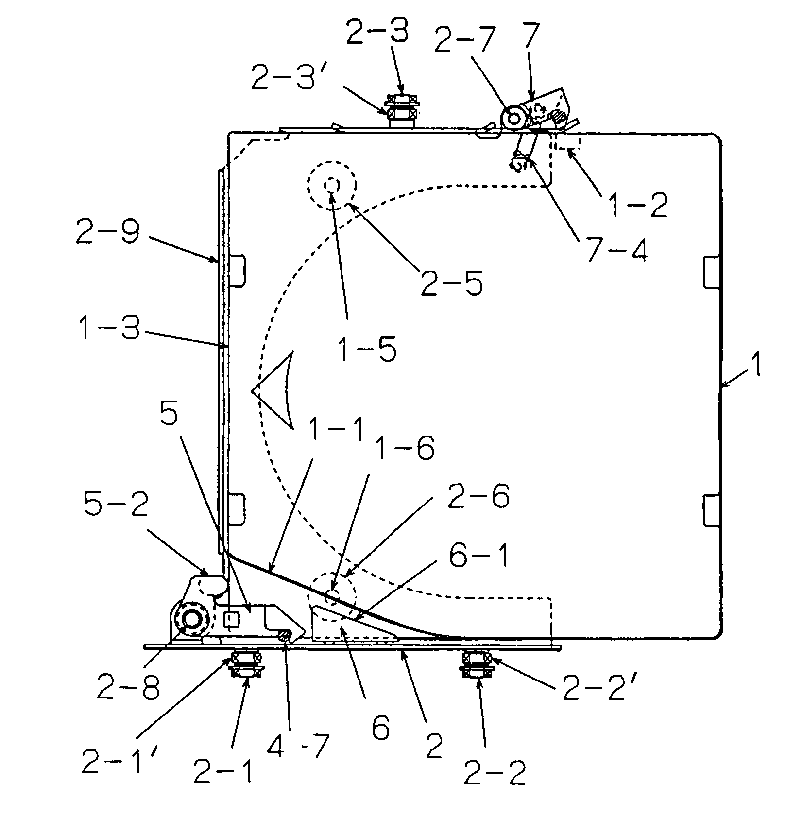
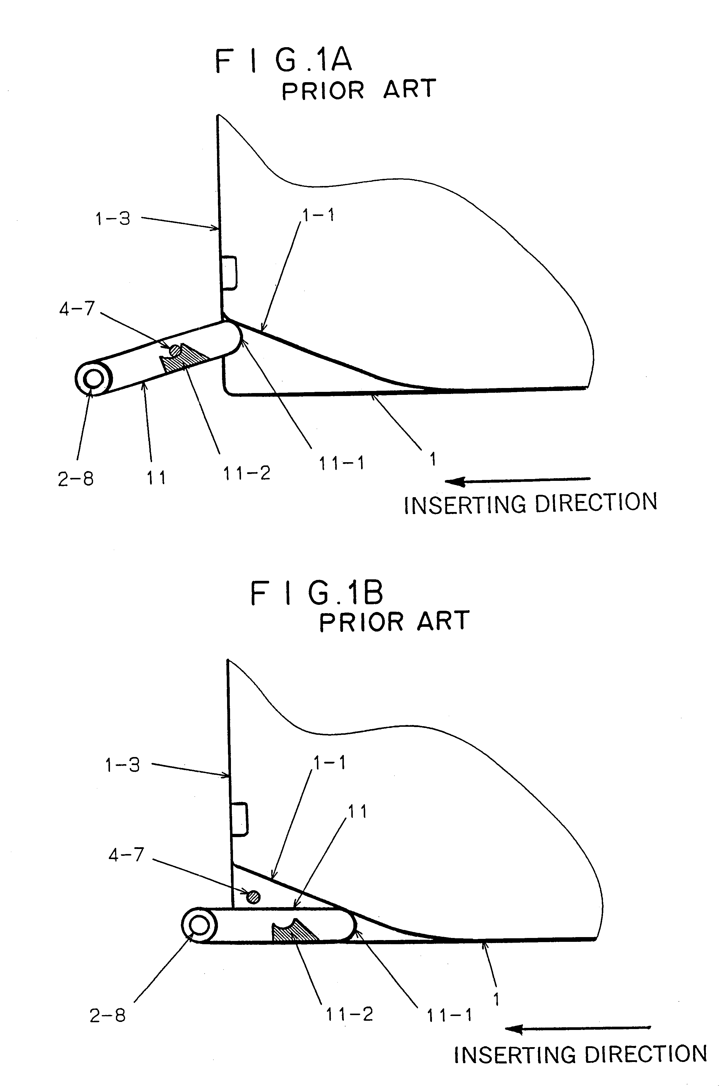
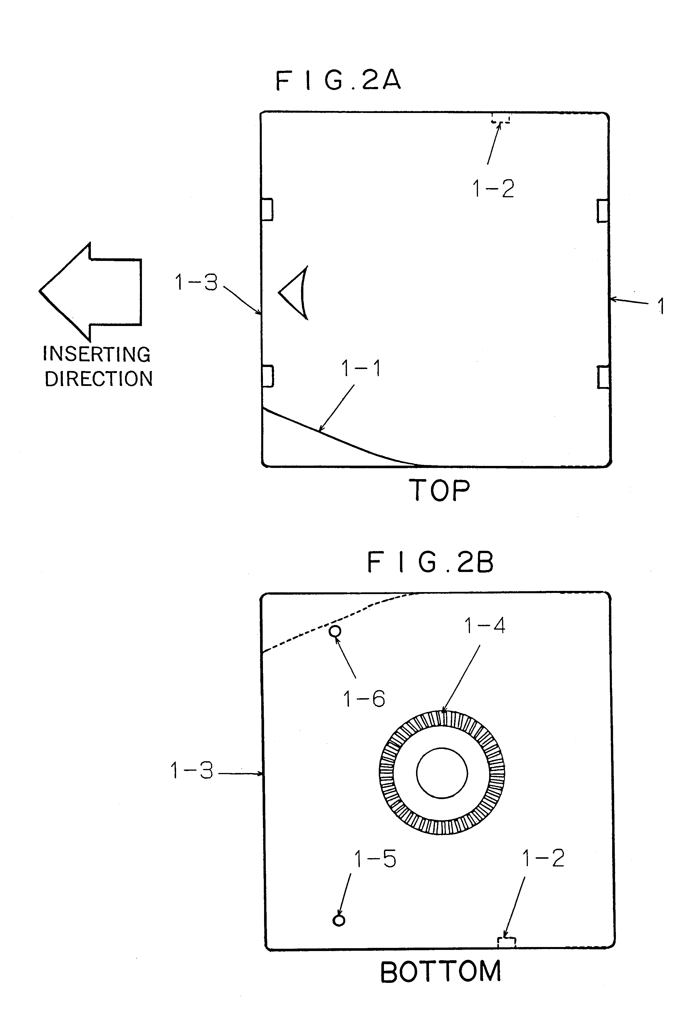
Referring FIGS. 2A and 2B, notch 1-1 is formed on the left side surface in the inserting direction of a magnetic tape cartridge 1. Lock hole 1-2 is formed at a lower portion on the right side surface of the magnetic tape cartridge 1. End surface 1-3 is formed in the inserting direction on magnetic tape cartridge 1. End surface 1-3 is a flat surface. Reel face gear 1-4 and aligning holes 1-5 and 1-6 are disposed on the rear surface of magnetic tape cartridge 1.

A loading mechanism loads magnetic tape cartridge 1. The loading mechanism is composed of cartridge tray 2 (shown in FIGS. 3A to 3D), loader plate 3 (shown in FIGS. 6A to 6D), and loader guide plate 4 (shown in FIGS. 7A to 7D). Cartridge tray 2 holds magnetic tape cartridge 1. Loader plate 3 slidably moves cartridge tray 2. Loader guide plate 4 has a guide groove on which cartridge tray 2 and loader plate 3 slidably move....


PUM

PropertyMeasurementUnit
angleaaaaaaaaaa
structureaaaaaaaaaa
rotationaaaaaaaaaa

Abstract

A cartridge mis-insertion preventing mechanism, comprising: a cartridge tray into which a cartridge is insertable; a loader plate into which the cartridge tray is insertable; a cartridge locking mechanism for locking the cartridge to the cartridge tray; a loading locking mechanism for preventing the cartridge tray and the loader plate from being inserted into a loader guide plate; and a restricting mechanism for changing the loading locking mechanism from a lock state to an unlock state only when the cartridge has been inserted into the cartridge tray in a correct direction; wherein the cartridge tray and the loader plate are inserted into the loader guide plate along with the cartridge when the cartridge is further inserted after the loading locking mechanism has been changed from the lock state to the unlock state; wherein before the cartridge is inserted into the cartridge tray, the cartridge locking mechanism is in an unlock state; wherein when the cartridge tray and the loader plate along with the cartridge have been inserted into the loader guide plate, the cartridge locking mechanism is changed from the unlock state to a lock state; and wherein before the cartridge is inserted into the cartridge tray, the loading locking mechanism is in the lock state.

Description

1. Field of the InventionThe present invention relates to a mechanism for preventing a cartridge from being inserted in the incorrect direction and in particular, the mechanism for use with a magnetic tape apparatus.2. The Prior ArtFIG. 1 shows the structure of a conventional tray locking mechanism. Referring to FIG. 1, lock lever 11 is rotatably mounted on a cartridge tray with pin 2-8. In the state that a cartridge has not been inserted, since lock lever securing portion 11-2 disposed on lock lever 11 is pressed to lock pin 4-7 with a predetermined means (not shown), lock lever 11 prevents the cartridge tray from being moved (this state is referred to as loading lock). In this state, since lock lever 11 protrudes, unless cartridge 1 is inserted in the correct direction, front end portion 11-1 blocks the cartridge, thereby preventing cartridge 1 from being loaded. On the other hand, when cartridge 1 is inserted in the correct direction, front end portion 11-1 is raised along notch ...

Claims


Application Information

Patent Timeline
Patent Type & Authority Patents(United States)
IPC IPC(8): G11B17/04G11B15/675
CPCG11B17/0434
Inventor TSUCHIYA, MANABUKAWASAKI, TOSHIMITSU
Owner NEC PLATFORMS LTD
Why Eureka
Try Eureka