Directional drilling apparatus and method utilizing eccentric stabilizer

a technology of eccentric stabilizer and drilling apparatus, which is applied in the direction of drilling accessories, drilling machines and methods, directional drilling, etc., can solve the problems of motor co stall, the well trajectory may deviate, and the drilling in this manner without rotation of the drill string may be very time-consuming, so as to prevent accidental disengagement

Inactive Publication Date: 2001-11-27
ANDERGAUGE
View PDF18 Cites 36 Cited by
  • Summary
  • Abstract
  • Description
  • Claims
  • Application Information

AI Technical Summary

Benefits of technology

Preferably, the stabiliser is of a larger gauge than the non-rotating offset mass. Accordingly, the non-rotating offset mass is held clear of the bore wall and depends from the string. The stabiliser is preferably of the same gauge as the bore or is of slightly smaller gauge than the bore.
Preferably, the orientation control means includes a mandrel for connection to the drill string with the offset mass being rotatable on the mandrel, the mass being connectable to the eccentric stabiliser element. In one embodiment, the mass may be fixed relative to the eccentric stabiliser element such that the element may only assume a single orientation within a bore, in another embodiment, the eccentric stabiliser element may be positioned in one of two orientations relative to the offset mass, to turn the bore to the "left" or "right"; if such an apparatus is provided in conjunction with a conventional adjustable stabiliser the driller may utilise the apparatus to control the bore azimuth and the stabiliser to control the bore inclination, in the preferred embodiment, the mass may be disengaged from the stabiliser element to permit the relative positions thereof to be varied as desired, and thus vary the orientation of the stabiliser relative to the bore and permit drilling of a bore or varying inclination and azimuth solely by means of the apparatus.
It is preferred that disengagement and re-engagement of the mass and stabiliser element may be executed remotely, from the surface, to avoid the requirement to retract the drill string from the bore. In one embodiment a clutch is provided between the mass and stabiliser element and may be disengaged by, for example, picking up the drill string. The clutch preferably has a locked configuration to prevent accidental disengagement. Locking and unlocking may be accomplished by any suitable means, including a drilling fluid actuated latch. Preferably, the clutch includes means for connecting the mandrel relative to the non-rotating stabiliser element and which operates on the clutch disengaging. This permits the eccentric element to be rotated to a desired orientation by rotation of the string. On the clutch re-engaging the connecting means disengages the element from the mandrel.

Problems solved by technology

However, if the string is stopped and then adjusted such that the motor bend is in a desired direction, rotating the drill bit using only the downhole motor will result in the trajectory of the well deviating.
Drilling in this manner without rotation of the drill string may be very time consuming as static friction between the non-rotating parts of the string and the bore wall tends to produce a stick-slip progression of the string through the bore.
This results in sudden increases in the weight (downward force) being applied to the bit and motor, causing the motor co stall.
This problem may even result in it becoming impossible to drill any further without rotating the drill string and is particularly acute in horizontal and extended reach wells.
However, the success of such apparatus has been limited as the mass provides an unstable support for the heavy drill string, such that the mass is likely to topple and be moved to one side by the string, which will tend to move downwards to occupy the lower part of the bore.

Method used


Image

  • Directional drilling apparatus and method utilizing eccentric stabilizer
  • Directional drilling apparatus and method utilizing eccentric stabilizer
  • Directional drilling apparatus and method utilizing eccentric stabilizer

Examples


Embodiment Construction

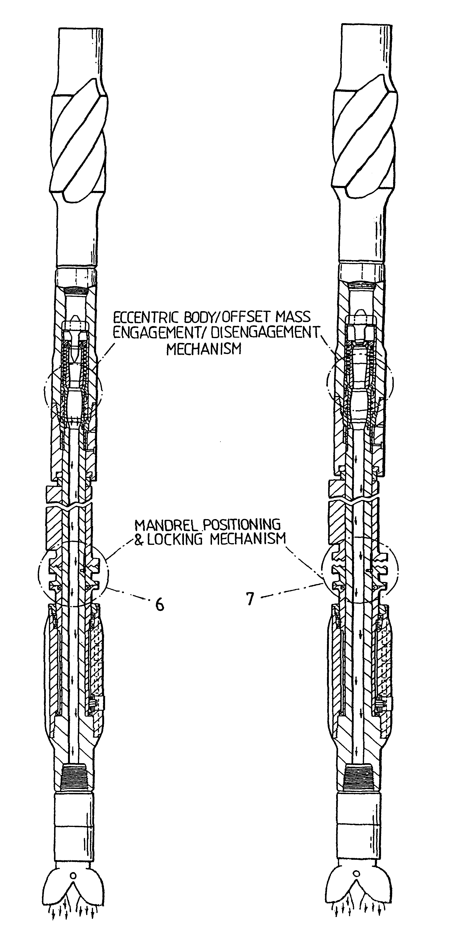
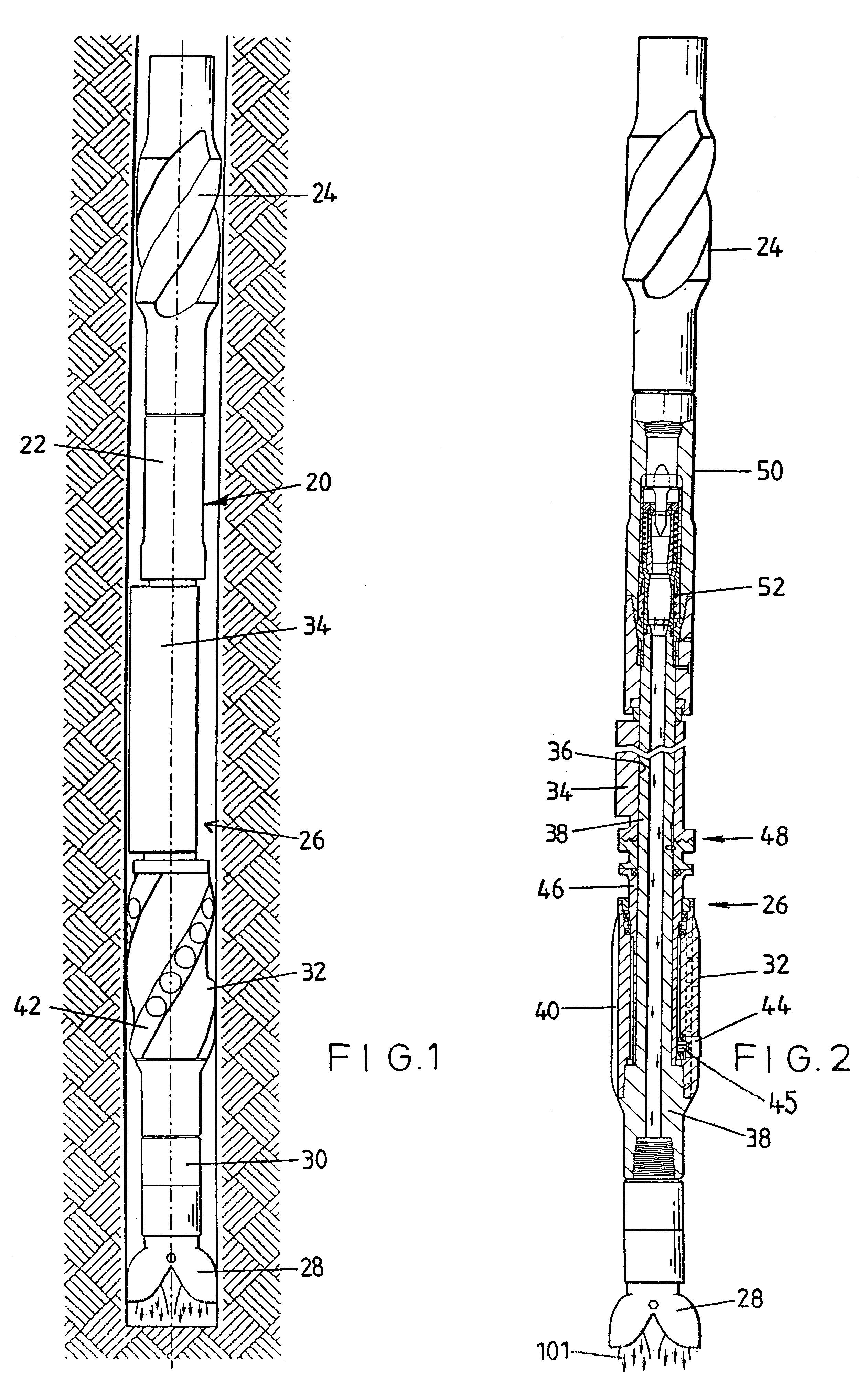
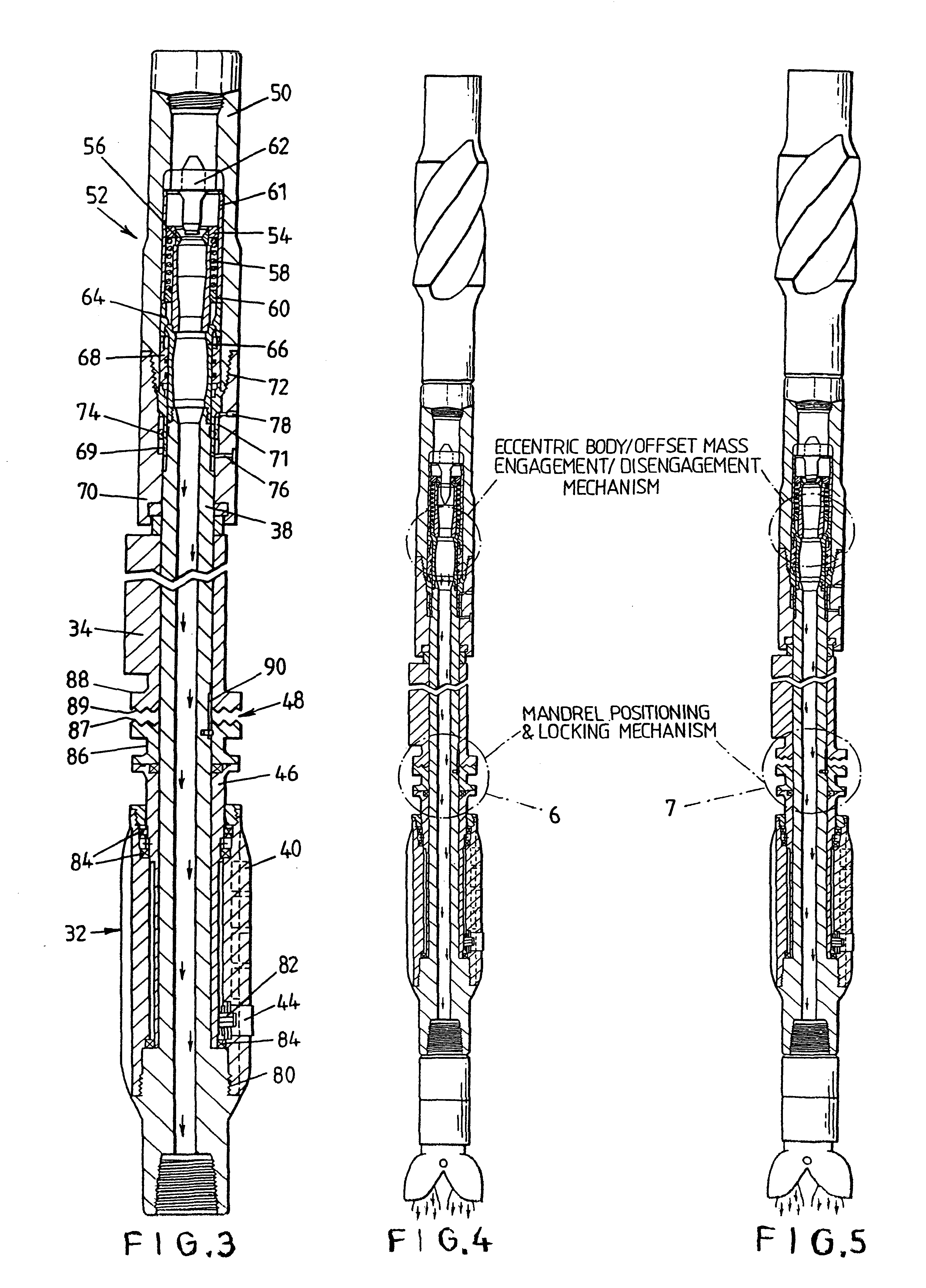
Reference is first made to FIG. 1 of the drawings, which illustrates the lower end of a drill string 20 located within a drilled bore 22. The string 20 includes a stabiliser 24, drilling apparatus in accordance with a first embodiment of the present invention in the form of a rotary steerable tool assembly 26, and a drill bit 28 joined to the tool assembly 26 by a connecting sub 30. The tool assembly 26 comprises a stabiliser 32 and orientation control means in the form of a non-rotating offset mass 34.

Reference is now also made to FIG. 2 of the drawings, which illustrates the tool assembly 26 in section. The main features and operation of the tool assembly 26 will be described initially, followed by a more detailed description of the individual elements of the assembly 26.

The offset mass 34 of the tool assembly 26 defines an offset bore 36 through which a tubular mandrel 38 extends. The mass 34 is free to rotate on the mandrel 38 and thus tends to remain in the same orientation whi...


PUM


Abstract

Directional drilling apparatus (26) for location on a drill string (20) comprises a stabilizer (32) having a mandrel (38) for connection to the drill string (20) and an eccentric non-rotating element (46) mounted on the mandrel (38) for offsetting the string (20) in the bore (22) and a non-rotating offset mass (34) for maintaining the element (46) at a selected orientation relative to the bore (22) as the drill string (20) rotates.

Description

This invention relates to drilling apparatus, and in particular to apparatus for use in directional drilling and a directional drilling method.In directional or controlled trajectory drilling, the S vertical inclination and azimuth of a drilled bore may be controlled such that the bore may extend from the surface to a target area which is not vertically aligned with the point on the surface where drilling commences. This permits a wide area to be accessed from a single drilling location and is therefore particularly useful in offshore drilling operations.Rotation of the drill bit mounted on the lower end of the drill string is achieved by rotation of the entire drill string, by a turntable on the surface, and often also by a downhole motor located on the drill string adjacent the bit. The downhole motor is usually driven by the drilling fluid which is pumped through the string. Steerable downhole motors include a "bent" housing or elbow which introduces a small deviation (around 1.d...

Claims


Application Information

Patent Timeline
Patent Type & Authority Patents(United States)
IPC IPC(8): E21B7/06E21B17/00E21B17/10E21B7/04E21B7/08
CPCE21B7/062E21B17/1014
Inventor EDDISON, ALAN MARTYN
Owner ANDERGAUGE
Why Eureka
Try Eureka