Acoustic panels and the like

Inactive Publication Date: 2001-11-27
RUSSELL ROBERT LINDSAY
View PDF4 Cites 32 Cited by
  • Summary
  • Abstract
  • Description
  • Claims
  • Application Information

AI Technical Summary

Benefits of technology

It is also an object of this invention to provide a means for and a method of facilitati

Problems solved by technology

It is known, for instance, to paint murals directly onto acoustic panels, but because of the labour intensive nature of such decoration, it is difficult for the mural or other artistic work to be removed from the panel or to be changed.
In addition, because of the nature of the artistic work, considerable time can elapse between the commissioning of the work and wh

Method used


Image

  • Acoustic panels and the like
  • Acoustic panels and the like

Examples


Example

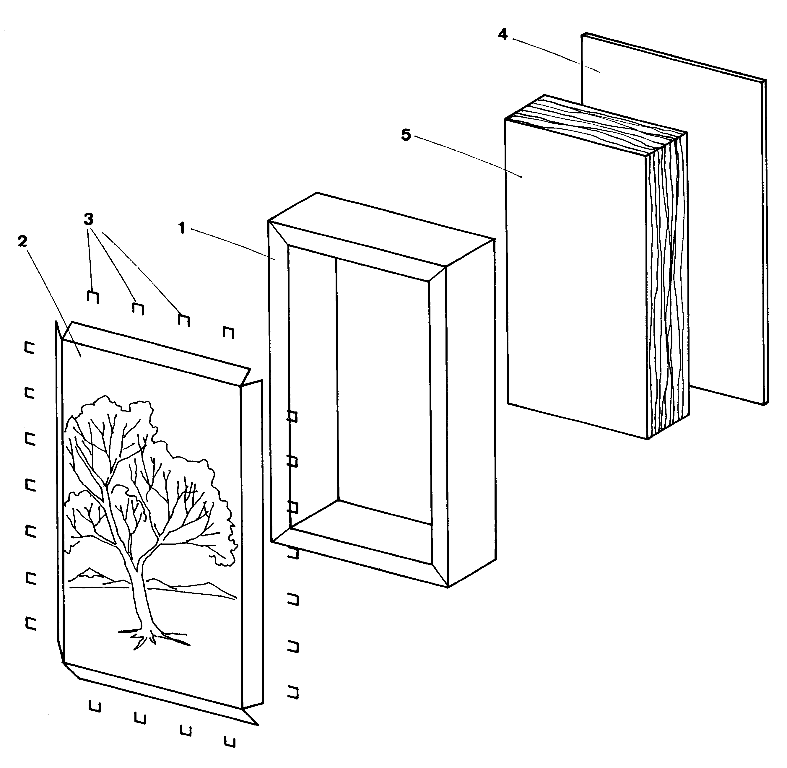
As illustrated in the drawings, a typical panel according to this invention includes a frame 1 which may be composed of lengths of timber suitably joined to form a rectangular or other desired shaped frame. A membrane 2 which may be a thin airtight canvas or similar membrane is suitably attached to one face of the frame. Various means of attaching the membrane to the acoustic panel can be utilised and in a highly preferred form as illustrated the membrane is attached to the frame of the acoustic panel by staples 3 or the like. Preferably the membrane is attached to the panel in a manner that it can be readily detached and replaced by another membrane as required.

The membrane is formed of a material that can be imprinted with an image. Preferably the image is imprinted onto the membrane by using a computer driven or electronic type printer that is capable of printing an image on a major portion of the surface of the membrane. In a highly preferred form, the image is stored or produce...


PUM


Abstract

An acoustic panel is constructed of a rectangular frame (1). A first face of the panel is covered by a membrane (2) which is at least substantially transparent to audio frequency sound waves. The interior of the frame (1) behind the membrane (2) includes sound absorbent material (5). The second face of the panel is covered by a closure member (4) which is opaque to audio frequency sound waves.

Description

This invention relates to acoustic panels and in particular but not exclusively to sound control panels.BACKGROUND TO THE INVENTIONAn acoustic panel is generally of a standard dimension and is used in architectural situations to assist in the absorption of sound, and also in the field of sound reverberation, echo and room acoustic problems generally.A typical acoustic panel consists of a framework which is covered on one or both faces by a decorative material. When the acoustic panel is to act as a sound absorbing panel it generally consists of a perimeter frame which can include suitable bracing and the like to rigidise the frame. A suitable sound absorbing core is positioned within the frame so that sound waves impinging on the material will be absorbed or at least attenuated. The frame is covered by a material which is intended to make the panel more aesthetically pleasing. Depending upon the usage to which the acoustic panel is to be put, the covering material on at least one fa...

Claims


Application Information

Patent Timeline
IPC IPC(8): E04B1/84E04B1/86
CPCE04B1/86E04B2001/8452
Inventor RUSSELL, ROBERT LINDSAY
Owner RUSSELL ROBERT LINDSAY
Why Eureka
Try Eureka