Oil skimming apparatus

Inactive Publication Date: 2002-10-29
ROCKWELL ROBERT JOHN
View PDF17 Cites 22 Cited by
  • Summary
  • Abstract
  • Description
  • Claims
  • Application Information

AI Technical Summary

Benefits of technology

Another objective of the invention is to facilitate the changing of scraper blades, which tend to wear out during use and thus require replacement. The port and starboard oil transfer troughs are preferably positioned substantially level with the rotational axis of the cylinder, to thereby facilitate changing of scraper blades by providing a relatively large opening between the transfer troughs and a top edge of the cylinder. The port and starboard transfer troughs can be placed above the rotational axis of the cylinder without affecting the amount of oil collected; however, if the troughs are placed too close to the top of the cylinder, it becomes necessary to remove the troughs in order to change the wiper blades, which can cost several days of down time. To further facilitate access for changing of scraper blades, the cylinder can be provided with an inner diameter of three to six feet or more. A larger cylinder also allows the apparatus of the invention to collect oil in high sea states. The inner and outer surfaces of the cylinder preferably have a scratch surface to thereby improve adhesion of oil

Problems solved by technology

Oil films are detrimental to the marine environment, and will damage shorelines if allowed to drift ashore.
Pole does not teach scrapping of a central baffle or the use of a unitary vessel having an in

Method used


Image

  • Oil skimming apparatus
  • Oil skimming apparatus
  • Oil skimming apparatus

Examples


Example

In the following detailed description of the preferred embodiments, reference is made to the accompanying drawings which form a part hereof, and in which are shown by way of illustration specific embodiments in which the invention may be practiced. It is to be understood that other embodiments may be utilized and structural changes may be made without departing from the scope of the present invention.

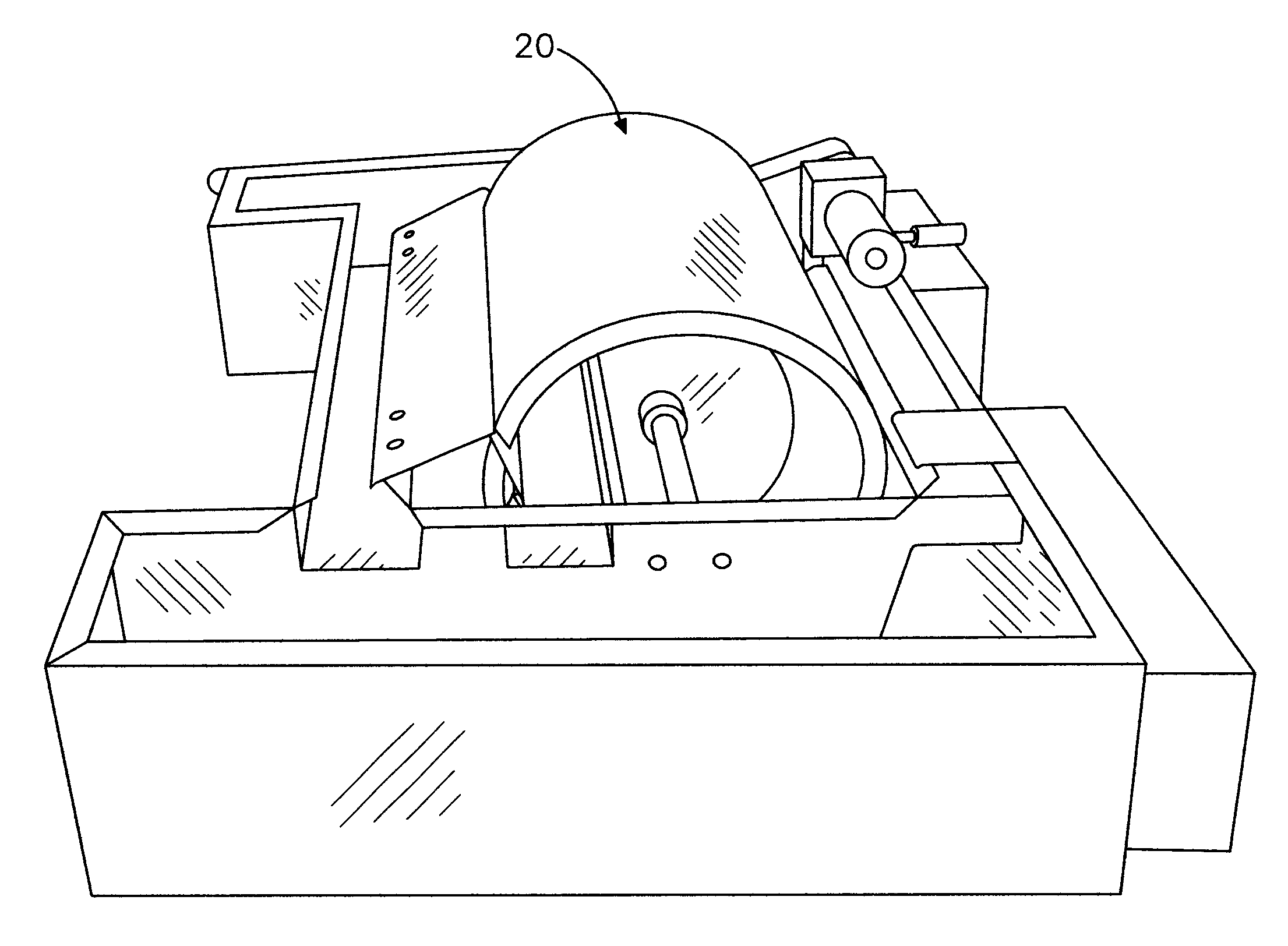
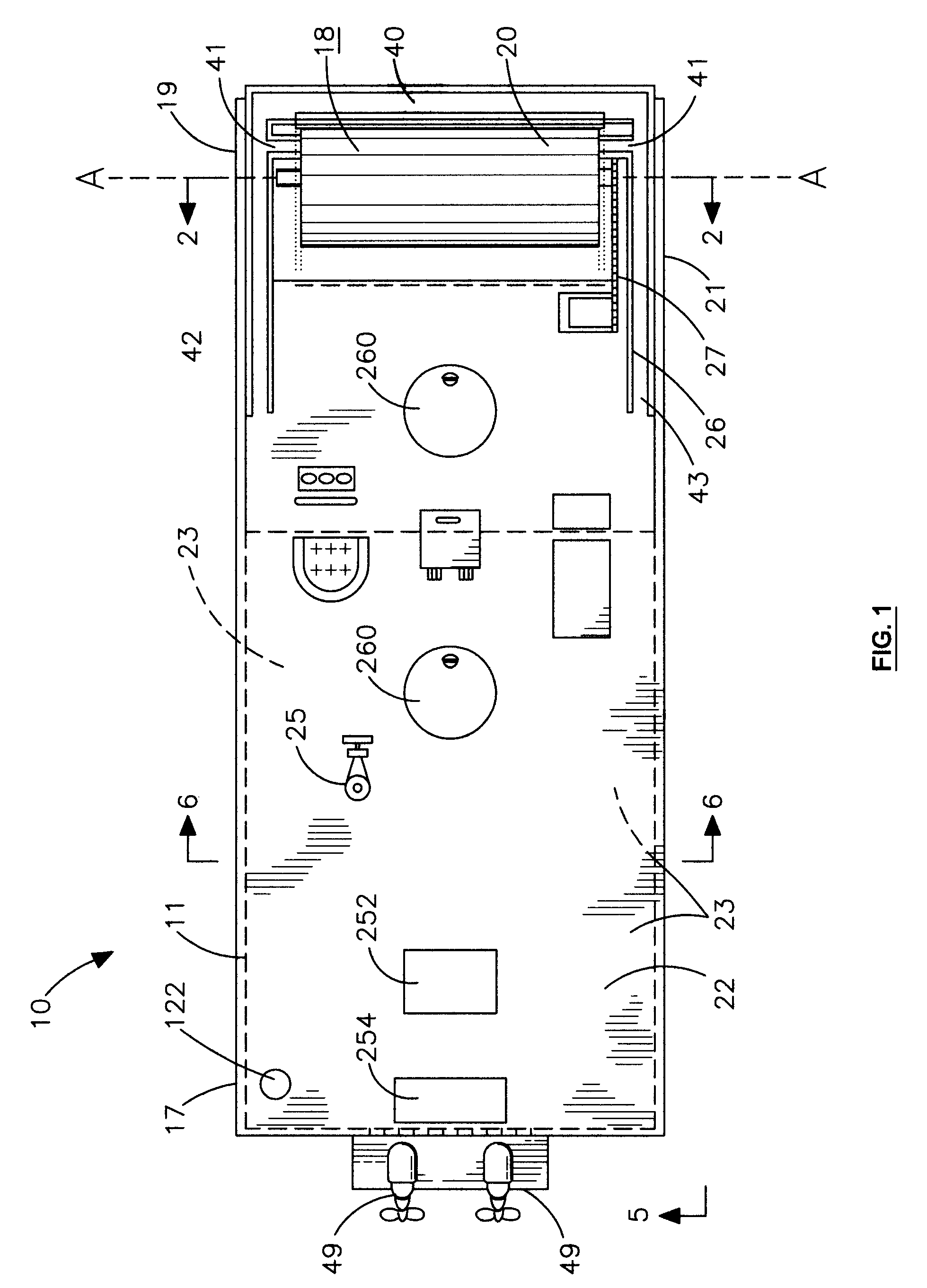
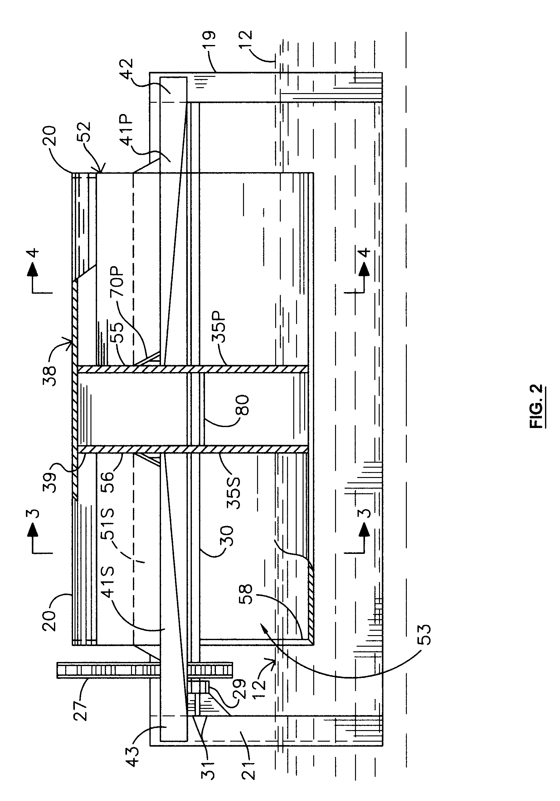
As shown in FIG. 1, the oil skimming apparatus 10 for collecting oil from a surface 12 of a water body comprises, generally, a floatable hull 11, a hollow cylinder 20 rotatably mounted adjacent a bow of the hull 11, and an arrangement of scrapers 50, 51P, 51S and troughs 40, 41P, 41S, 42, 43 for scraping oil from the inner 39 and outer 39 surfaces of the cylinder 20 and transporting the collected oil to an oil collection tank 22. The oil collection tank 22 is preferably fixed within the hull 11. A suction outlet 122 is preferably provided for use in pumping collected oil from the oil co...


PUM


Abstract

An oil skimming apparatus for collecting oil from a surface of a water body is provided comprising a floatable hull, a hollow non-floating cylinder rotatably mounted adjacent a bow of the hull, and an arrangement of scrapers and troughs for scraping oil from the inner and outer surfaces of the cylinder and transporting the collected oil to an oil collection tank. The cylinder has port and starboard open ends, which allow oil to collect on the inner surface of the cylinder during rotation. A pair of bulkheads are fixed inside of the cylinder. A pair of pontoons extend fore of the bow of the floatable hull. The pontoons are spaced apart to form an oil collection area. The cylinder is rotatably mounted in the oil collection area via a drive shaft-member passing through the port and starboard bulkheads.

Description

The present invention relates to apparatuses for removing spilled oil from the surfaces of water bodies, and more particularly to apparatuses and methods for removing oil using drum skimmers.When oil is spilled into a water body, such as from a damaged oil tanker, the spilled oil forms a thin film on the surface of the water body. This film is sometimes referred to as an oil slick or sheen. Oil films are detrimental to the marine environment, and will damage shorelines if allowed to drift ashore. The following is a summary of the many different apparatuses and methods have been developed for collecting spilled oil from the surface of water bodies.The closest known prior art is U.S. Pat. No. 5,030,363 (Pole), which differs significantly from the present invention. Pole describes an oil retrieving vessel having a cylindrically shaped collection surface. Preferably, the cylindrically shaped collecting surface is a drum having closed ends. The drum is preferably watertight and is light ...

Claims


Application Information

Patent Timeline
IPC IPC(8): B63B35/32E02B15/04E02B15/10
CPCB63B35/32E02B15/103Y10S210/923Y02A20/204
Inventor ROCKWELL, ROBERT JOHN
Owner ROCKWELL ROBERT JOHN
Why Eureka
Try Eureka