
Method and device for calendering a paper web

a paper web and calendering technology, applied in the field of calendering paper webs, can solve the problems of increased calender blackening, negative effect of operating parameters on the web, and inability to utilize the above process, so as to improve the quality of winding paper, improve the effect of calender quality and low loss of volume to the paper web

Inactive Publication Date: 2010-02-02
VOITH PATENT GMBH
View PDF28 Cites 0 Cited by
  • Summary
  • Abstract
  • Description
  • Claims
  • Application Information

AI Technical Summary

Benefits of technology

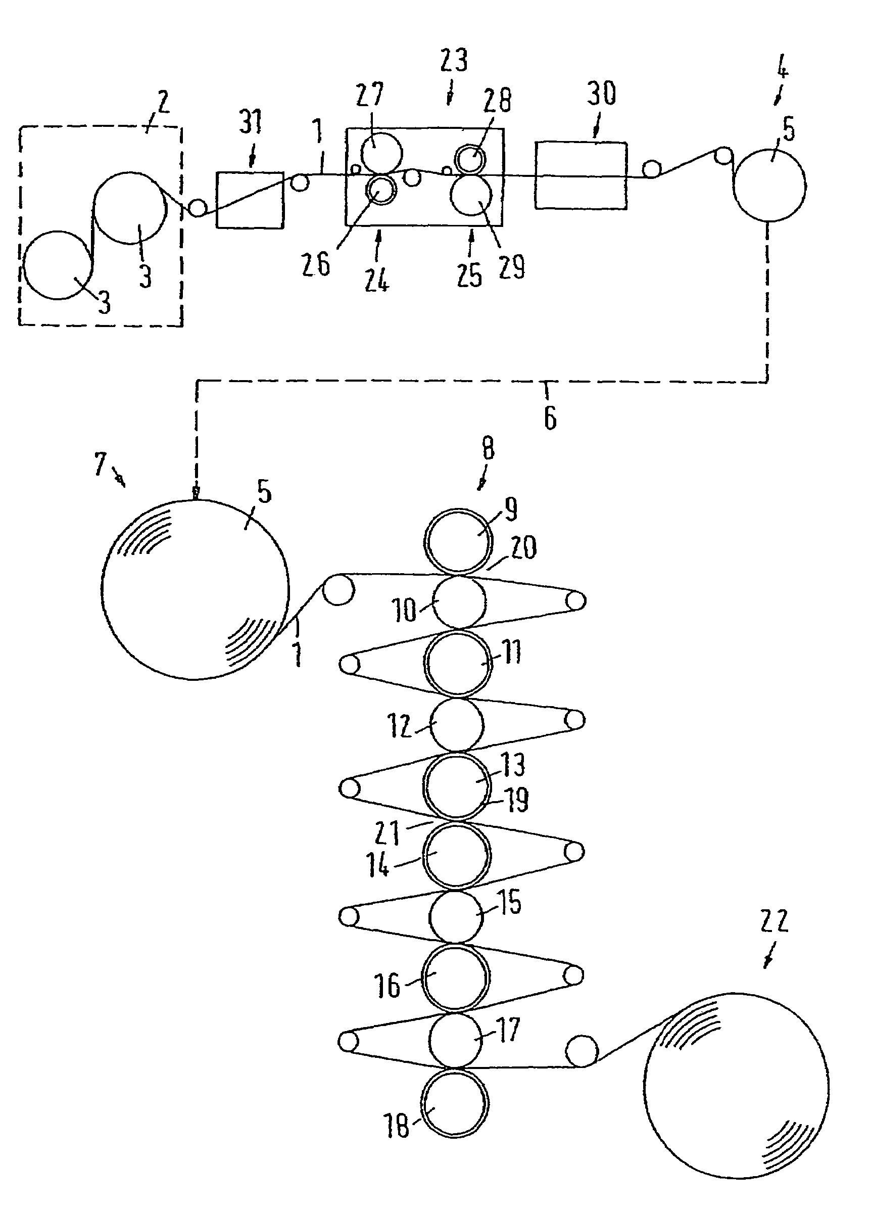
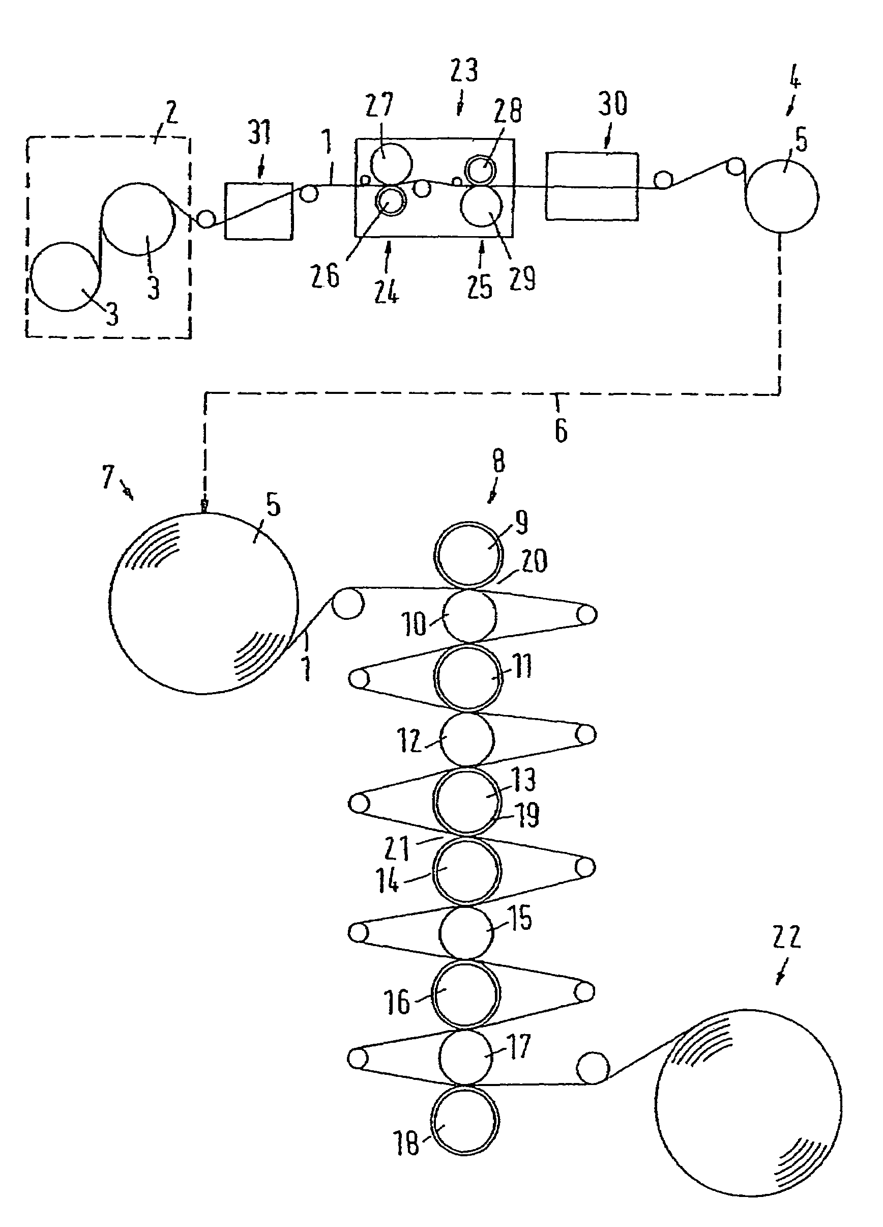
The invention is about improving the calendering process in a paper machine to increase production speed. By pre-calendering the paper web in an off-line calender before winding it up, the paper machine can operate at higher speeds. The pre-calendering involves heating the paper web with a hard roller to facilitate the calendering process. The paper web is then transported to an off-line calender and passed through it. The process also includes adding moisture to the paper web to compensate for any pressure or temperature effects. The paper web can be calibrated in the calendering unit to improve its quality and winding efficiency. The invention also mentions the use of different types of nips and the importance of reducing two-sidedness and the number of rollers used in the calendering unit. Overall, the invention provides a more efficient and effective way to calender paper in a paper machine.

Problems solved by technology

However, to reach the desired surface quality for SC-A or SC-B-Plus papers the above process cannot be utilized.
This change in the operating parameters may have negative effects on the web, such as a higher calender blackening.
Increasing the speed of production could also require operating the calender with more rollers, such as 12 rollers, resulting in increased overall costs of manufacturing.
In extreme cases, the installation of a third off-line calender may be necessary, which again result in increased manufacturing cost.
In particular, the increased costs would include the preparation of a standing surface for the third calender.

Method used


Image

  • Method and device for calendering a paper web
  • Method and device for calendering a paper web

Examples


Embodiment Construction

[0029]The particulars shown herein are by way of example and for purposes of illustrative discussion of the embodiments of the present invention only and are presented in the cause of providing what is believed to be the most useful and readily understood description of the principles and conceptual aspects of the present invention. In this regard, no attempt is made to show structural details of the present invention in more detail than is necessary for the fundamental understanding of the present invention, the description taken with the drawings making apparent to those skilled in the art how the several forms of the present invention may be embodied in practice.

[0030]The FIGURE shows schematically a paper web 1 manufactured in a paper machine 2. The paper web 1 is dried in a drying station 3 and wound onto a drum 5 at a winding station 4. Examples of higher-value paper may include SC-A or SC-A-Plus paper. Drum 5 is transported via a transport path 6, shown in the FIGURE as a bro...


PUM

PropertyMeasurementUnit
temperatureaaaaaaaaaa
surface temperatureaaaaaaaaaa

Abstract

The present invention shows a process and device of calendering a web. The process includes drying the web and winding the web at the end of a production section. The process includes transporting the wound web to at least one off-line calender, unwinding the web and passing the web through the at least one off-line calender. Further, the process includes treating the web between drying and winding of the web in at least one on-line calendering unit. Further still, the process includes at least one on-line calendering unit includes at least one nip defined by at least one hard roller. The instant abstract is neither intended to define the invention disclosed in this specification nor intended to limit the scope of the invention in any way.

Description

CROSS-REFERENCE TO RELATED APPLICATIONS[0001]The present application claims priority under 35 U.S.C. §119 of German Patent Application No. 10 2004 020 069.6, filed on Apr. 24, 2004, the disclosure of which is expressly incorporated by reference herein in their entireties.BACKGROUND OF THE INVENTION[0002]1. Field of the Invention[0003]The invention relates to a method for calendering a paper web, which is wound after drying performed at the end of a production section, and then transported to an off-line calender, unwound and passed through the calender.[0004]2. Discussion of Background Information[0005]A method for calendering a paper web is used in conjunction with the manufacture of high-quality papers, such as SC-A papers or SC-A-Plus papers, in which high demands are imposed on the quality of the surface of the web. To ensure adequate printability in the gravure process, certain aspects of paper surface qualities are required.[0006]In order to ensure such quality, off-line calen...

Claims


Application Information

Patent Timeline
Patent Type & Authority Patents(United States)
IPC IPC(8): D21G1/00B30B3/04
CPCD21G1/00
Inventor KOHNEN, JOSEFCRAMER, DIRK
Owner VOITH PATENT GMBH
Learn More