Pneumatic apparatus and method for transporting irregularly-shaped objects

Inactive Publication Date: 2001-11-27
GABRIELE DINO
View PDF10 Cites 32 Cited by
  • Summary
  • Abstract
  • Description
  • Claims
  • Application Information

AI Technical Summary

Benefits of technology

The present invention provides a method and apparatus for transporting large, irregular objects upwardly, then horizontally, then downwardly. The invention provides an apparatus for pneumatically transporting objects comprising: a) a main duct having an input opening for introducing the object, and an output opening; b) a fan communicating with the main duct through a fan duct for drawing air out of the main duct upstream from the output opening; c) first valve means for selectively opening or

Problems solved by technology

It is undesirable to transport such beverage cans for recycling at ground level through the supermark

Method used


Image

  • Pneumatic apparatus and method for transporting irregularly-shaped objects
  • Pneumatic apparatus and method for transporting irregularly-shaped objects
  • Pneumatic apparatus and method for transporting irregularly-shaped objects

Examples


Embodiment Construction

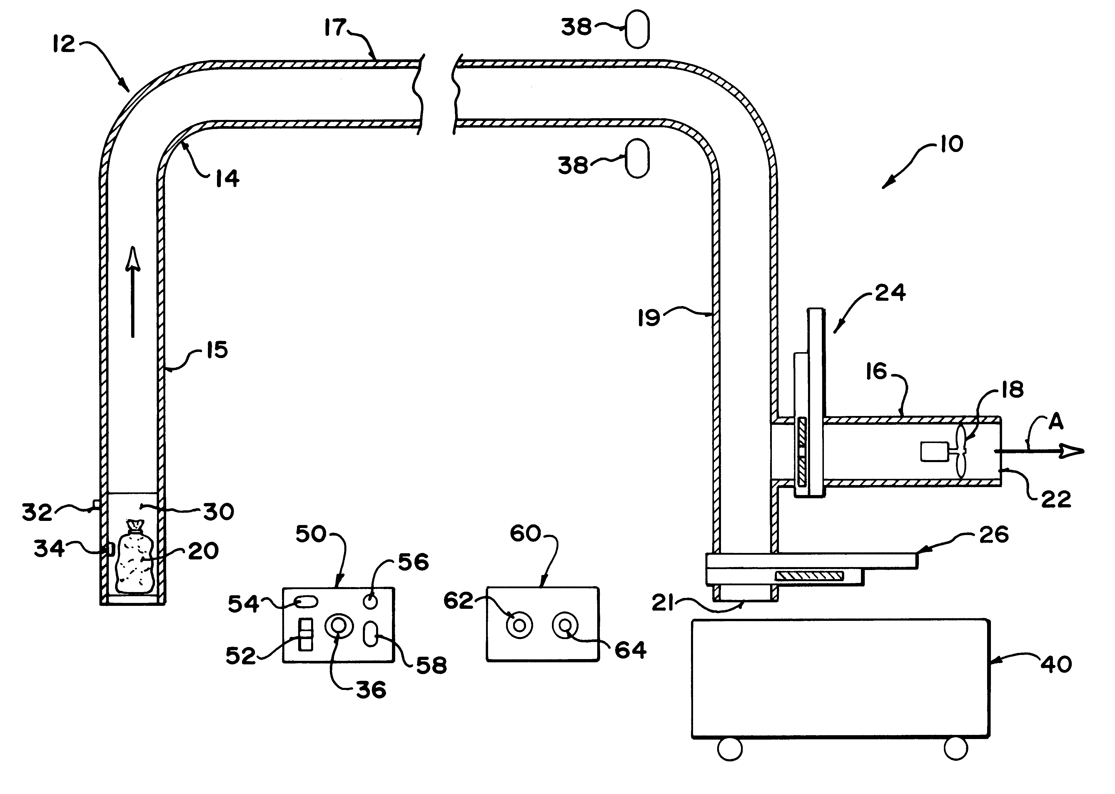
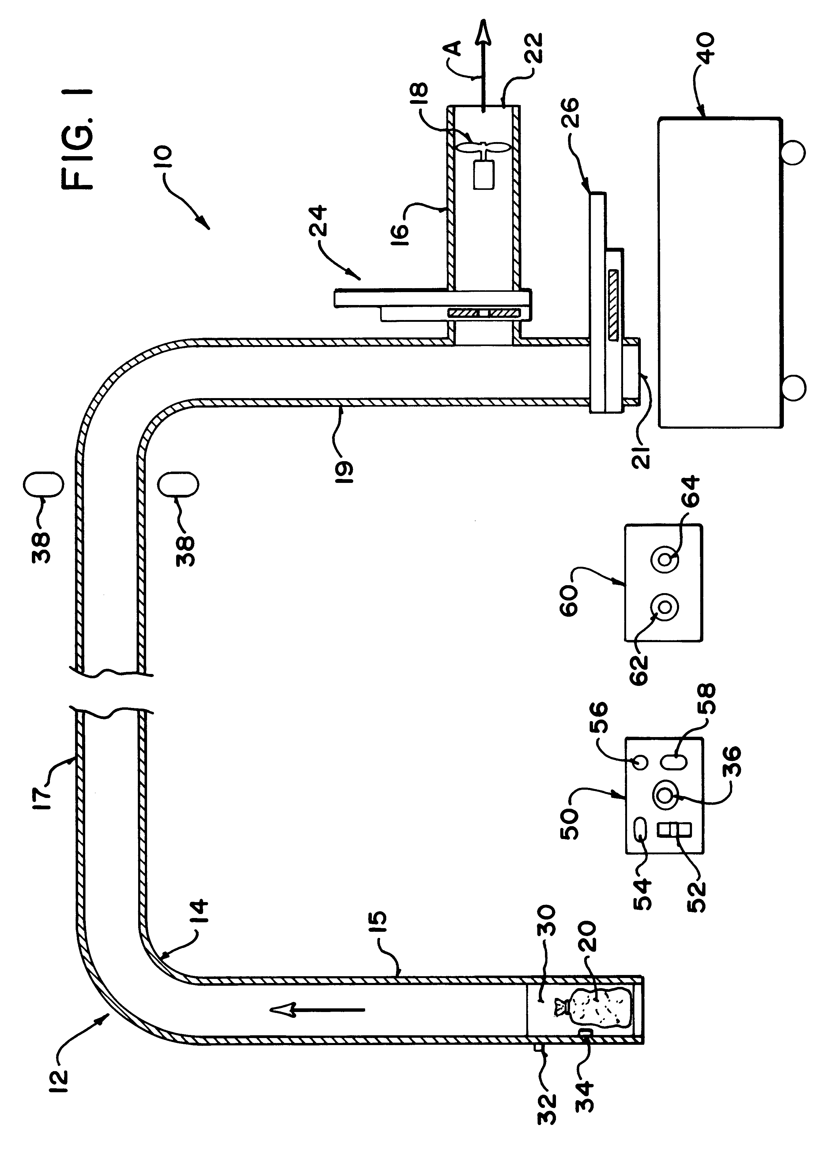
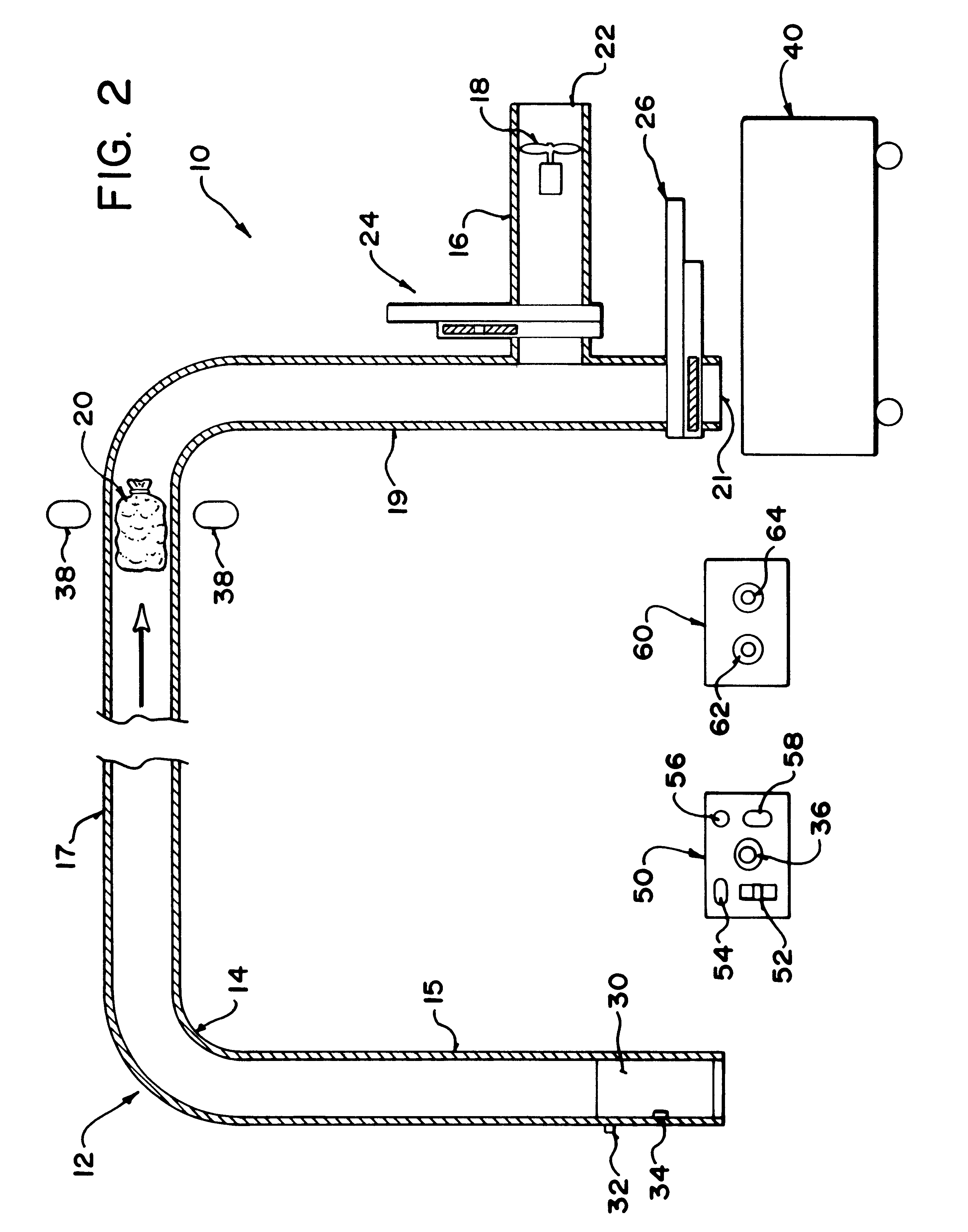
With reference to the drawings, the pneumatic transport system of the invention, generally designated by 10, comprises a series of relatively air-tight pneumatic tubes or ducts 12, comprising a main duct 14 and a fan duct 16 in which is mounted fan 18 for blowing air out of the main duct 14 as shown by arrow A. Fan 18 is a large, powerful fan, for example a 15 horsepower Twin City fan model # 222 BAF-SW, which operates continuously as long as the system is switched "on". The end 22 of fan duct 16 opens to the atmosphere. Main duct 14 has a vertical launch section 15, horizontal section 17, vertical end section 19, and outlet opening 21 and has a preferred diameter of 20 inches. An object 20 is to be transported, which will be for example a large, tied plastic (polyethylene) garbage bag, typically 19 inches in diameter when filled, filled with empty aluminum cans for recycling. Such objects are of irregular shape, in that their outer dimensions are not fixed or uniform as would be a ...


PUM


Abstract

A pneumatic system for transporting irregular objects such as bags filled with recycled cans through a duct in which the object is first accelerated by pneumatic pressure and subsequently decelerated after a sensor triggers the closure of the air outlets as the object approaches the output point of the system.

Description

The invention relates to the field of transportation of objects by pneumatic tubes or ducts, and more particularly to transportation of large, irregular objects such as bags of recycled material by pneumatic tube.Pneumatic tubes or ducts have long been used in the transportation of small, uniform solid objects such as hollow cases or canisters for transporting mail within a building. The use of pneumatic tubes or ducts has also been applied to the transport of bags of rubbish. For example, U.S. Pat. No. 3,853,355 Buisson issued Dec. 10, 1974 discloses a system for discharging rubbish through pneumatic ducts. This system is designed for transporting bags of unsorted household waste in which the bags are heavy and irregular and sometimes leaking sticky substances, so the main problem to be overcome by that system was to provide sufficient momentum to transport the bags of rubbish to the central destruction facility. This was done by having the bag of rubbish travel downwardly, then ho...

Claims


Application Information

Patent Timeline
IPC IPC(8): B65G51/00B65G51/20B65G51/02
CPCB65G51/02B65G51/20
Inventor GABRIELE, DINO
Owner GABRIELE DINO
Why Eureka
Try Eureka