
Louver member and method

a technology of louver and member, which is applied in the field of louver member and method description of embo, can solve the problems of difficult to reach louver in houses, ineffective wooden louver, dissatisfactory homeowners, etc., and achieves the effect of simple hand-held tools, easy assembly and manufacture, and flexible size and shape of the louver assembly

Inactive Publication Date: 2001-11-27
DARCEY MIKE E
View PDF10 Cites 3 Cited by
  • Summary
  • Abstract
  • Description
  • Claims
  • Application Information

AI Technical Summary

Benefits of technology

Thus, with the problems and disadvantages of conventional louvers, the present invention was conceived and one of its objectives is to provide a weatherproof louver member which can be cut to size and installed on-site to form a louver assembly.
It is still another objective of the present invention to provide a louver member and method of use which allows flexibility in the size and shape of the louver assembly formed.
It is also an objective of the present invention to provide louver members which are manufactured for on-site delivery and which can be cut and installed using simple hand tools.
It is yet a further objective of the present invention to provide a louver member which is relatively inexpensive to manufacture and can be self-installed by relatively unskilled workers.
The method of installation allows the user to cut a first louver member to a desired length using simple hand tools and thereafter to cut succeeding louver members to successively shorter lengths such as in the construction of a triangular louver assembly. Each individual louver member is then attached to a truss or the like with conventional fasteners to form the louver assembly. When completed the louver assembly is difficult to distinguish from conventional siding and does not detract from the building's appearance.

Problems solved by technology

Such louvers often distract from the appearance of a building or mobile home and are distasteful to homeowners and others.
The wooden louver is effective for ventilation but unsightly and must be constantly maintained with paint or the like to protect it and prevent it from deteriorating.
Oftentimes such louvers in houses are difficult to reach due to their height and are left unattended for many years, ultimately having to be completely replaced.
When completed the louver assembly is difficult to distinguish from conventional siding and does not detract from the building's appearance.

Method used


Image

  • Louver member and method
  • Louver member and method
  • Louver member and method

Examples


Embodiment Construction

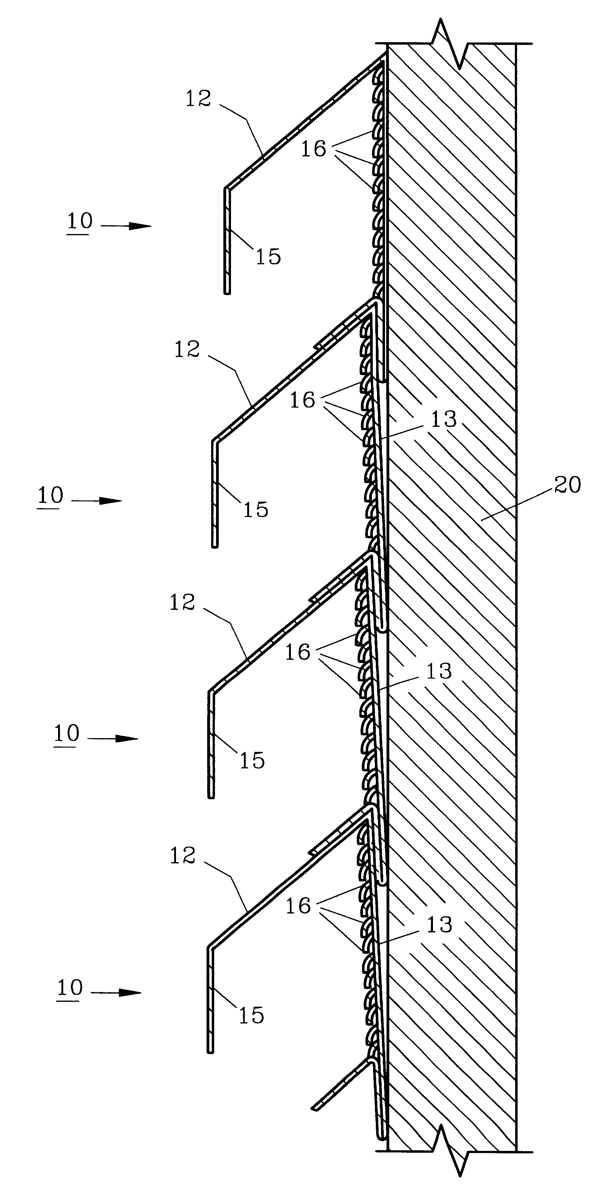
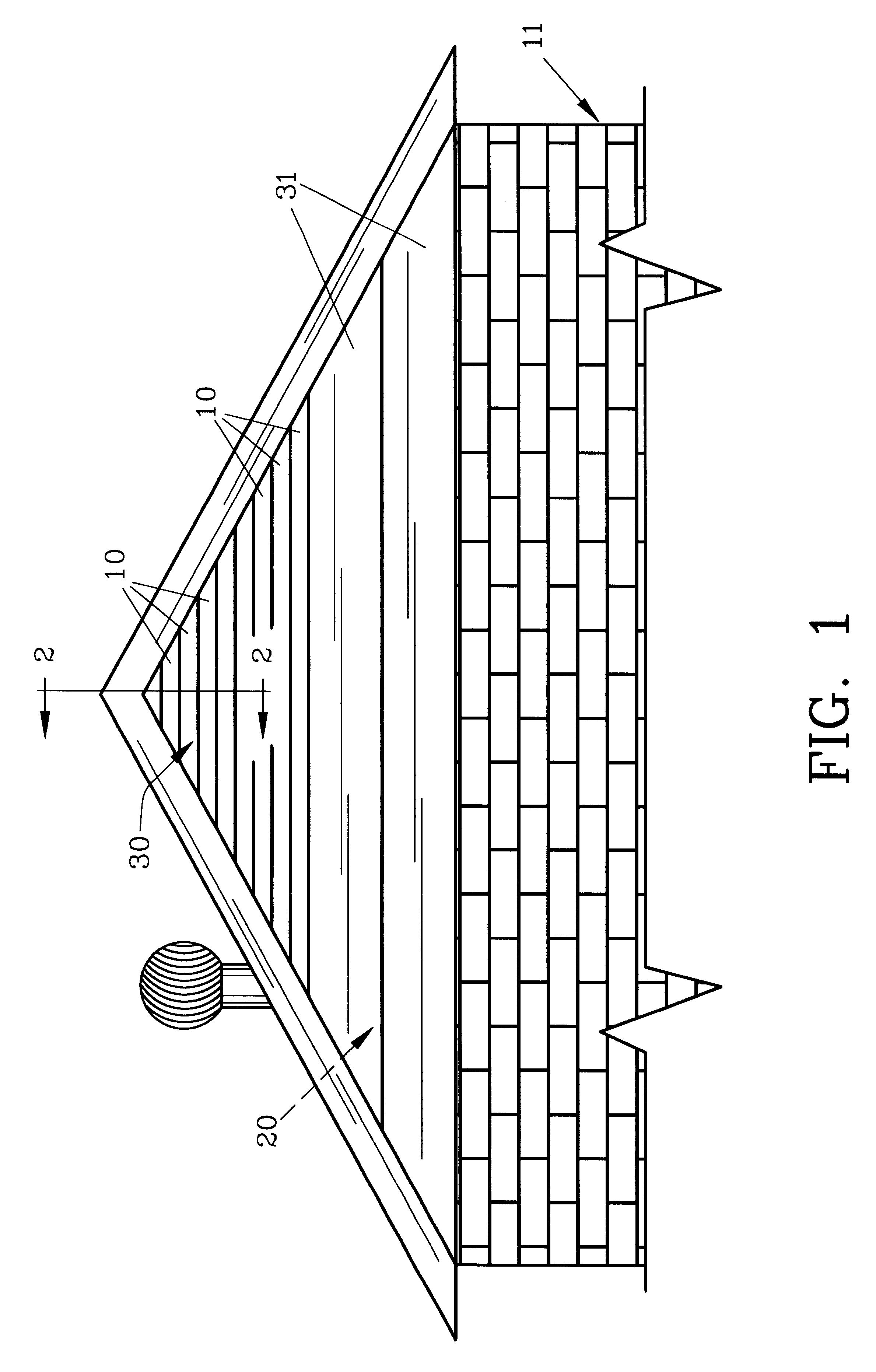
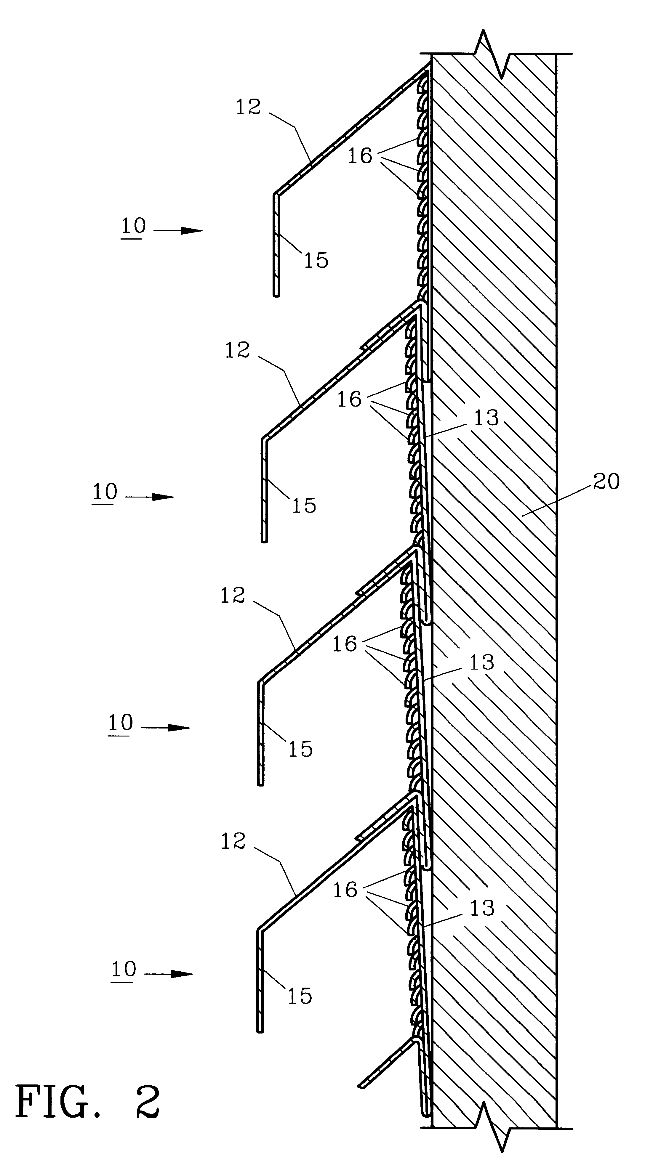
For a more detailed explanation of the invention and its method of use, turning now to the drawings, FIG. 1 demonstrates in schematic form preferred louver members 10 attached to form louver assembly 30 on the end of attic 20 of house 11. Louver members 10 which form louver assembly 30 may be for example, formed preferably such as by extrusion of aluminum in twelve foot (3.66 m) sections for on-site cutting and installation. As seen in FIG. 2, louver members 10 have a general inverted V-shape with an elongated front section 12 and an elongated rear section 13 integrally formed such as by conventional extrusion or molding processes. Front section 12 includes a bent or downwardly directed portion 15 near the distal end thereof. Downward directed portion 15 is parallel to rear section 13. Louver members 10 are attached to supports such as roof truss member 20 such as by nails, staples, screws or otherwise. Truss member 20 is part of a usual roof truss system formed from wooden two-by-f...


PUM


Abstract

A louver member is provided for forming louver assemblies for houses and other buildings for ventilation purposes. The method of installing the louver members includes cutting to size and attaching the same to roof trusses for on-site louver assembly. Each louver member has a somewhat inverted V-shape with a front and an apertured rear to allow air passage.

Description

The invention herein pertains to louvers for ventilating buildings and particularly pertains to elongated preformed louver members used in on-site louver assembly.DESCRIPTION OF THE PRIOR ART AND OBJECTIVES OF THE INVENTIONHouses, manufactured homes and other buildings require ventilation to prevent excess heat build-up and deterioration of building structures. Builders of houses and mobile home manufacturers often purchase triangle, octagon, square or other slatted louvers formed from wood, plastic, metal and the like. Openings are then framed on-site and the purchased louvers installed. Such louvers often distract from the appearance of a building or mobile home and are distasteful to homeowners and others. For example, a home which is finished with aluminum siding may have an attic louver formed from wood. The wooden louver is effective for ventilation but unsightly and must be constantly maintained with paint or the like to protect it and prevent it from deteriorating. Oftentime...

Claims


Application Information

Patent Timeline
Patent Type & Authority Patents(United States)
IPC IPC(8): F24F13/08
CPCF24F13/082
Inventor DARCEY, MIKE E.
Owner DARCEY MIKE E
Learn More