Test blade

a technology of blades and blades, applied in the field of test blades, can solve the problems of blades affecting the trailing blade and the surrounding engine casing at high speed, blades becoming detached from the hub, affecting the trailing blade and the surrounding engine casing, etc., and achieve the effect of reducing delamination

Active Publication Date: 2017-12-05
ROLLS ROYCE PLC
View PDF8 Cites 2 Cited by
  • Summary
  • Abstract
  • Description
  • Claims
  • Application Information

AI Technical Summary

Benefits of technology

[0011]By providing a channel on the radially inner surface of the root portion, the ease of manufacture of the test blade is improved because it is much easier to machine a channel into the surface of the root portion than drill bores into the root portion. This means that it is possible to apply the invention to either a straight-rooted blade or to a curved-rooted blade. The open nature of the channel (compared to a bore within the root portion) allows flexibility in the size, position and orientation of the explosive charges. Furthermore, by positioning on or proximal the camber line and thus spacing it from the pressure and suction faces of the blade, the structural integrity and strength of the root portion is maintained. The load carrying capability of the root portion is improved as stresses in the test blade are reduced. The quantity of explosive in the charge can be reduced which leads to less secondary explosive damage.
[0022]In some embodiments, the pressure and / or suction face(s) of the root portion comprise a coating for reducing the effect of localized contact stresses on the sub-surface of the root-portion. The coating may be formed, for example, of glass reinforced plastic (GRP) or carbon fibre reinforced plastic (CFRP).
[0026]The test blade may be reinforced in the thickness (circumferential) direction to reduce delamination using stitching (e.g. Kevlar stitching) in a region proximal the root portion.
[0044]The groove may have a narrower width towards the radially outer surface of the hub such that the root potion is held in compression upon application of centrifugal force. Where the channel in the root portion contains a charge carrier, the charge carrier is also held under compression which increases the load carrying capability of the root section.
[0053]The method may comprise reinforcing the blade in the thickness / circumferential direction in a region proximal the root portion using stitching (e.g. Kevlar stitching) to reduce delamination,

Problems solved by technology

This results in the blade impacting its trailing blade and surrounding engine casing at high speed.
This causes the blade to become detached from the hub, and to impact its trailing blade and surrounding engine casing.
When the above-described test is used with a metallic blade, the explosive charge detonation results in a crack that propagates linearly through the shortest section of the blade which bears the critical failure load and the blade fails in tension under the centrifugal force.
However, it can be difficult to accurately machine a curved hole for the explosive charge and detonators that are required for a curved rooted blade.
Due to the structure of a composite blade, a number of problems occur when the above described method is used to release a composite blade.
In particular, when the blade fails due to the explosion, a linear crack does not propagate through the blade, as happens for a metallic blade.
However, when using explosives, the energy causes the surrounding resin to vaporise, overcoming the weak bonds between composite layers.
This means that extensive delamination occurs throughout the blade and the structural integrity of the blade is significantly compromised, which may result in a test result that is less than the desirable “worst case”.
However, the Kevlar stitching requires a number of small holes to be drilled through the blade which reduces the strength of the blade in the radial direction, and also reduces its resistance to twisting.

Method used


Image

  • Test blade
  • Test blade
  • Test blade

Examples


first embodiment

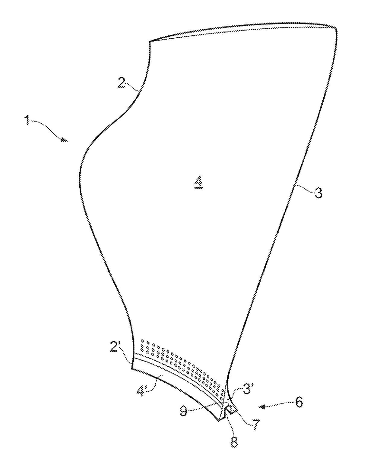
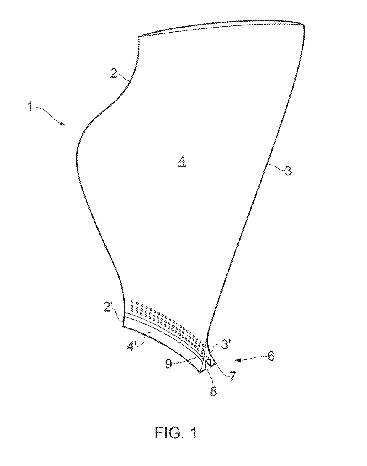
[0070]a test blade 1 is shown in FIGS. 1 and 2.

[0071]The blade 1 comprises a radially extending leading edge 2 and trailing edge 3 axially spaced by a (concave) pressure surface 4 and a circumferentially opposed (convex) suction surface 5. The camber line extends from the leading edge 2 to the trailing edge 3 of the blade 1 midway between the pressure and suctions surfaces 4, 5 of the blade 1.

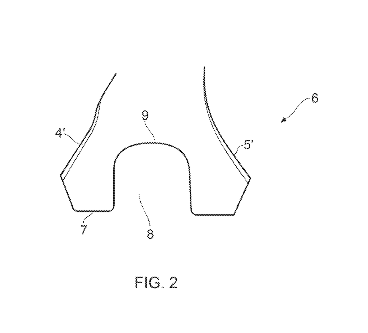
[0072]The blade 1 has a root portion 6 for mounting on a rotatable hub 10 (shown in FIG. 3).

[0073]The root portion 6 comprises a radially inner surface 7 having a channel 8 extending along the entire length of the camber line of the radially inner surface 7 to the leading edge 2′ and the trailing edge 3′ of the root portion 6.

[0074]By providing a channel on the radially inner surface 7 of the root portion 6, the ease of manufacture of the test blade 1 is improved because it is much easier to machine a channel 8 into the surface of the root portion than drill bores into the root portion 6. This ...

second embodiment

[0091]In the second embodiment shown in FIGS. 7 and 8, the root portion 6 further comprises axially extending slots 22 extending from both the leading and trailing edges 2′, 3′ on both the suction surface 5′ and pressure surface 4′ of the root portion 6.

[0092]Each axially extending slot 22 extends through the root portion 6 in the thickness (circumferential) direction (from the pressure surface 4′ or the suction surface 5′ of the root portion 6) to join the channel 8.

[0093]The axial slots 22 in the second embodiment are to provide areas of radial weakness at the axially outer ends of the channel which is where, in use, the detonators are positioned. The force of the explosion is reduced in these areas (by the absence of explosive charge) and the slots are provided to ensure cleaving of the blade from the root portion in these areas especially in static tests (where no centrifugal force is applied to the test blade).


PUM

PropertyMeasurementUnit
thicknessaaaaaaaaaa
thicknessaaaaaaaaaa
thicknessaaaaaaaaaa

Abstract

A test blade for use in a blade-release test in which the blade is mounted on a rotatable hub and at least a portion of the blade is released therefrom by the action of a controlled explosion. The blade has a root portion for mounting on said rotatable hub and the root portion comprises a radially inner surface having a channel extending at least partly along or proximal the camber line. The channel is for receiving at least one explosive charge and at least one detonator which may be contained within a charge carrier.

Description

FIELD OF THE INVENTION[0001]The present invention relates to a test blade and / or to a method of preparing a test blade and is concerned particularly, but not exclusively, with a fan blade modified for an explosive release test, and / or to a method for preparing such a blade.BACKGROUND[0002]A gas turbine jet engine includes a number of sets of blades that are mounted on rotational hubs. These include fan blades, turbine blades and compressor blades, all of which rotate at high speed. In use, it is possible, although extremely unlikely, for a blade or part of a blade to become detached from the hub on which it is mounted whilst rotating. This results in the blade impacting its trailing blade and surrounding engine casing at high speed. Due to the mass and speed of the blade, the force at which impact occurs can be very high. It is therefore important that any damage caused by such an impact is not critical. Tests are therefore carried out to evaluate the damage which would be caused by...

Claims


Application Information

Patent Timeline
Patent Type & Authority Patents(United States)
IPC IPC(8): F01D21/04F01D5/18F01D5/30
CPCF01D21/045F01D5/18F01D5/3007Y10T29/49334F05D2240/30F05D2260/83Y02T50/672F05D2220/30Y02T50/60
Inventor WHITEHEAD, CHRISTOPHER MTHOMPSON, EWAN FMASON, PAUL JTURNER, JEREMY N
Owner ROLLS ROYCE PLC
Why Eureka
Try Eureka