
Tooling System With Array of Height Adjustable Elements

a tooling system and height adjustment technology, applied in the field of components, can solve the problems of inability to adjust inability to meet the needs of users, etc., and achieve the effect of facilitating the adjustment of the height of the element and allowing for flexibility in the position of the elemen

Inactive Publication Date: 2010-11-25
SURFACE GENERATION
View PDF20 Cites 3 Cited by
  • Summary
  • Abstract
  • Description
  • Claims
  • Application Information

AI Technical Summary

Benefits of technology

[0014]In one embodiment of the invention, the supporting element is formed from a resilient material, such as mild steel. Consequently, the element is readily machinable and inexpensive to produce. Alternatively, the supporting element may be formed from a resistant material such as polymer concrete. With this arrangement the supporting element can be readily cast and therefore formed to a net shape.
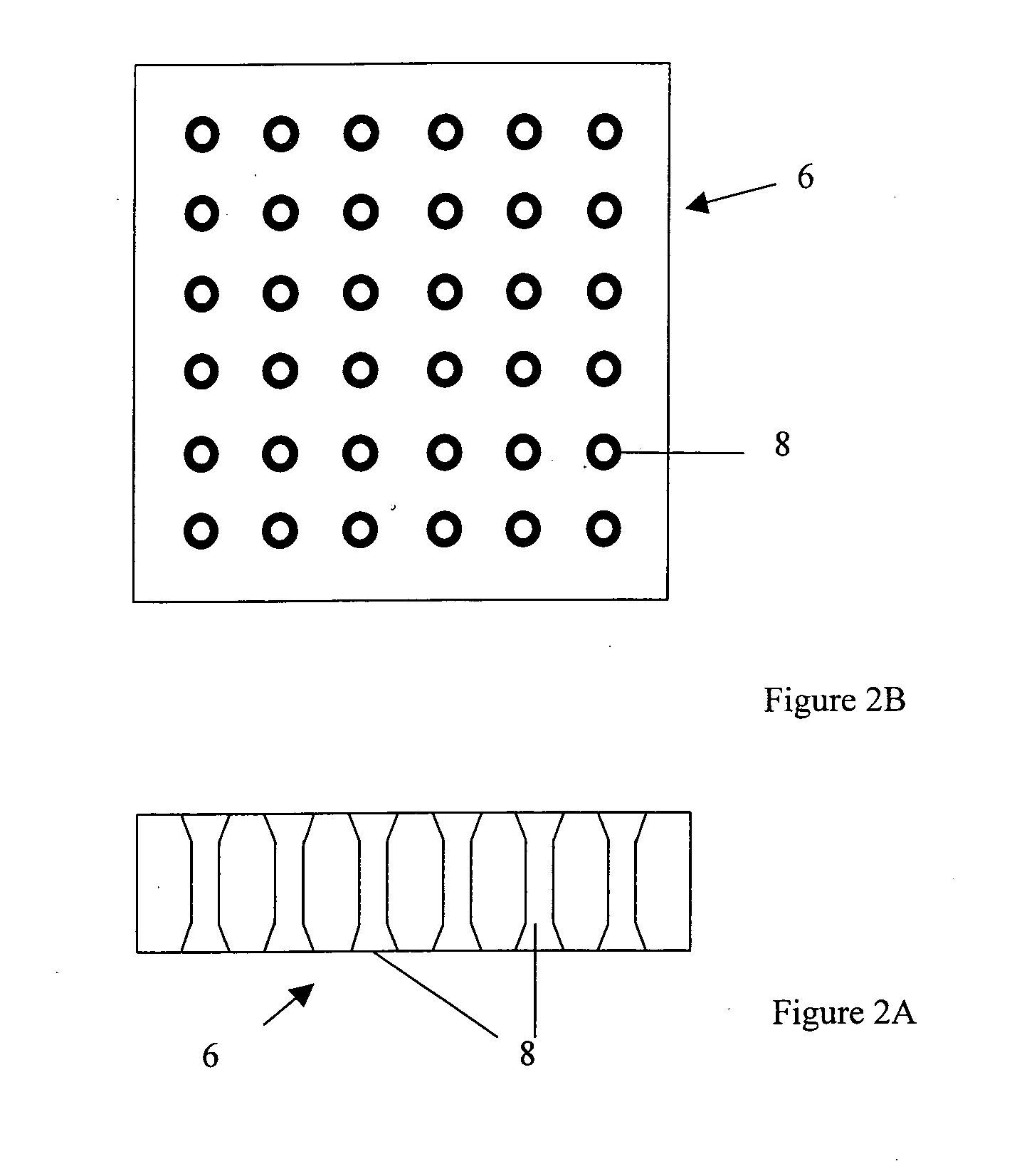
[0021]It is envisaged that the network of holes in the supporting element will enable some flexibility in the position of the elements in the array and therefore in operation there will be a number of spare holes that are not in use. The spare holes may be used to house ancillary equipment, for example actuators or sensors or means to expel the elements from the array.

Problems solved by technology

The support elements and the support rail will be placed under significant loading and this will mean a heavy load or bending force is applied to the support rail.
The longer the support rail the higher is the bending force and the result could be that some deformation of the support rail leading to inaccuracies or anomalies in the mould surface.
This, as will be appreciated, is not desirable.

Method used


Image

  • Tooling System With Array of Height Adjustable Elements
  • Tooling System With Array of Height Adjustable Elements
  • Tooling System With Array of Height Adjustable Elements

Examples


Embodiment Construction

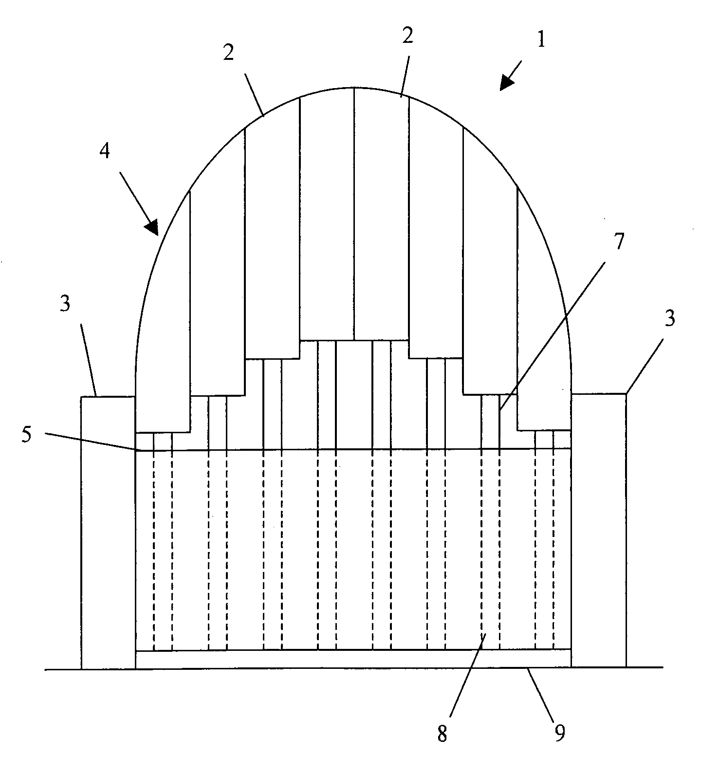
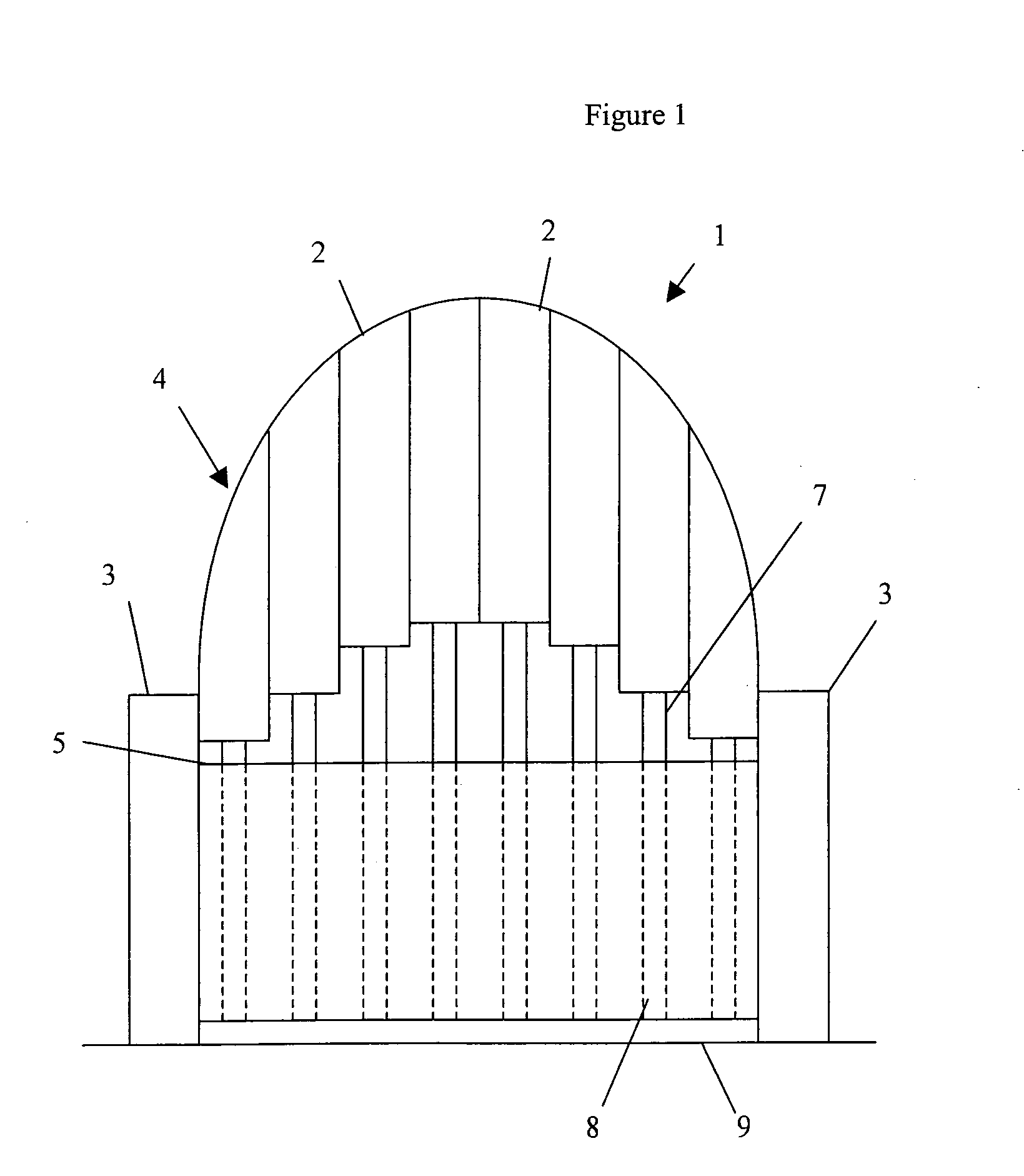
[0036]Now referring to FIG. 1 of the drawings, there is shown a schematic representation of a tooling system generally in accordance with the present invention. The tooling system 1 comprises a number of elements 2 formed into an array and disposed between the peripheral sidewalls 3 of a bolster element.

[0037]Each of the elements 2 includes a machinable portion, the upper section of the element and a fixed portion. The elements 2 of the array are mounted to support rails 5 which extend across the array between opposing sidewalls 3 of the bolster by means of screw threaded bolts 7.

[0038]The screw threaded bolts 7 are fixedly mounted to the fixed portion of the elements and is mounted in a screw threaded bore provided in the support rail 5. A supporting element 6 is disposed in the space below the support rails 5 and rests on a base 9. The supporting element 6 also contacts the lower surface of the support rails 5 and is provided with a network of holes 8 corresponding to the mounting...


PUM


Abstract

A tooling system (1) having a number of elements (2) arranged in an array, which elements define a contoured surface, or a section of a contoured surface. The tooling system also including means (7) for mounting an element to a support rail (5) which extends across the array, which means allows adjustment of the height of the element with respect to other elements of the array, and extends through the support rail into a space defined below the support rail. A supporting element (6) formed from a suitable resistant material and including accommodation means (8) for the means for mounting, is located in the space below the support rail and is sized so that it substantially vertically fills the space between the support rail and a base on which the tooling system is located.

Description

BACKGROUND OF THE INVENTION[0001]1. Field of the Invention[0002]The present invention relates to a component for use in a tooling system, and to an improved tooling system, including said component.[0003]2. Description of the Prior Art And Related Information[0004]The component is particularly suitable for use in the tooling systems generally described and claimed in PCT Patent Publication No. WO 2002 / 064308. This Patent document provides a description of the base technology for a tooling system from which the invention of the current Patent Application is generated.[0005]This PCT Patent Application describes a tooling system comprising a plurality of elements generally arranged in an array, each element of the array being moveable longitudinally of its length relative to the other elements of the array. The tooling system also includes means to adjust the longitudinal position of a respective element so that the array defines a desired surface contour; and means for retaining the e...

Claims


Application Information

Patent Timeline
IPC IPC(8): B23Q3/00
CPCB23Q3/00B23Q1/035
Inventor HALFORD, BEN JOHN
Owner SURFACE GENERATION
Learn More